


Chapter8—Patching
— Operation Guide 137
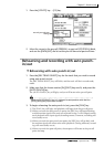
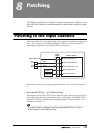
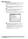
2. Move the cursor to the output jack whose patching you wish to change,
and use the [DATA/JOG] dial to select the signal that you wish to assign.
The following types of signal can be assigned to each output jack.
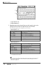
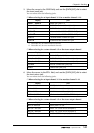
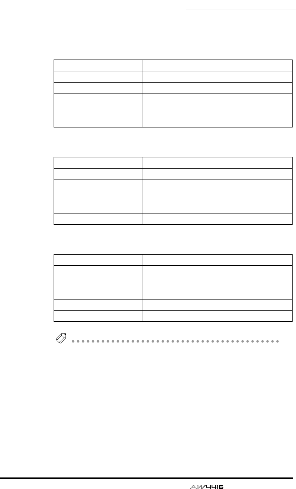
❍ OMNI OUT jacks 1–4
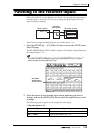
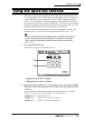
❍ DIGITAL STEREO OUT jack
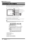
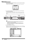
❍ STEREO OUT jacks
❍ Digital I/O card (slot 1) OUTPUT 1–8
❍ Digital I/O card (slot 2) OUTPUT 1–8
Tip!
When selecting a signal for assignment to an output jack, selections beginning with
“I-” such as “I-I8” or “I-M16” may be displayed in gray. Selections beginning with
“I-” indicate insert-out points of each channel. The gray display indicates that this
insert point is invalid. (For details on insert I/O patching, refer to page 140.)
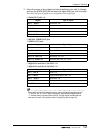
Display Type of signal
AUX 1 – AUX 8 AUX buses 1–8
RDR 1 – RDR16 Recorder direct out 1–16
ST L/ST R L/R channels of the stereo output channel
BUS 1 – BUS 8 Buses 1–8
DIR 1 – DIR16 Input channel direct out 1–16
Display Type of signal
ST L/R Stereo output channel
BUS 1/2 – BUS 7/8 Buses 1/2–7/8
DIR 1/2 – DIR15/16 Input channel direct out 1/2–15/16
AUX 1/2 – AUX 7/8 AUX buses 1/2–7/8
RDR 1/2 – RDR15/16 Recorder direct out 1/2–15/16
Display Type of signal
BUS 1 – BUS 8 Buses 1–8
DIR 1 – DIR16 Input channel direct out 1–16
AUX 1 – AUX 8 AUX buses 1–8
RDR 1 – RDR16 Recorder direct out 1–16
ST L/ST R L/R channels of the stereo output channel