


Chapter1—Welcome to the world of the AW4416
22 — Operation Guide
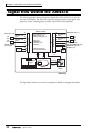
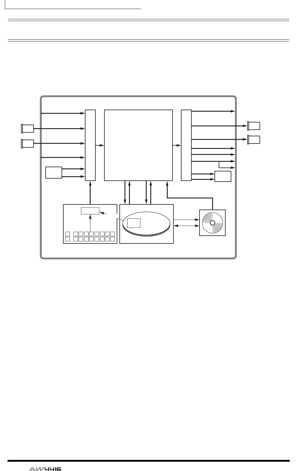
Signal flow within the AW4416
The following diagram shows the general signal flow of the AW4416. As you can
see from this diagram, the AW4416 consists of several sections: input patch, out-
put patch, mixer, sampling pads, recorder, and CD-RW drive (optional).
The signal flow within each section is explained in detail in the pages that follow.
Input channels 1–24
Effect returns 1/2
Monitor channels 1–16
Buses 1–8
STEREO bus
AUX buses 1–8
SOLO bus
Channel insert I/O
Stereo bus insert I/O
Output patch
Input patch
Mixer section
AW4416
Sampling pads section
Recorder section
×8
×8 ×16 ×16
×8
×4
×8
×2
×2 ×2
×2
×2
×2
×2
×2
×2
×8
×8
Trigger
CD Writing
Data Backup/
Restore
INPUT jacks 1–8
OMNI OUT jacks 1–4
MONITOR OUT jacks
PHONES jack
STEREO OUT jacks
DIGITAL STEREO OUT jack
Effect
1/2
Effect
1/2
D-RAM
1 2 3 4 5 6 7 8
1
A
B 2 3 4 5 6 7 8
Audio
File
Import
I/O
card
I/O
card
I/O
card
I/O
card
OPTION I/O
slot 1
OPTION I/O
slot 2
OPTION I/O
slot 1
OPTION I/O
slot 2
DIGITAL STEREO
IN connector
CD-RW
Drive