


Chapter1—Welcome to the world of the AW4416
— Operation Guide 25
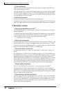
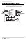
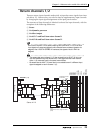
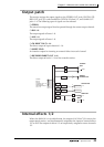
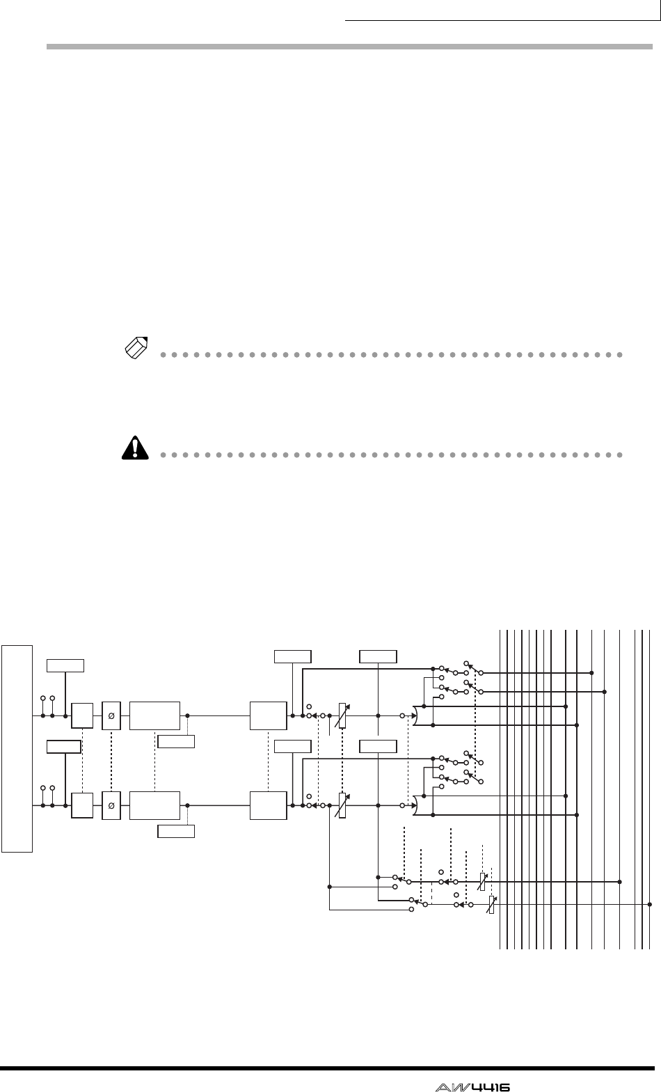
Return channels 1/2
These are stereo input channels used mainly to input the return signals from inter-
nal effects 1/2. However they can also be used as supplementary input channels
by changing the input signal assignments of the input patch section.
The structure of these channels is identical to that of the input channels, with the
exception of the following differences:
1 Stereo
B No dynamics processor
C No direct output
D No AUX 7 send level from return channel 1
E No AUX 8 send level from return channel 2
Tip!
Since return channels 1/2 are stereo, selecting MIC/LINE INPUT or OPTION IN as
input signals will cause two adjacent odd-numbered/even-numbered signals to be
assigned. Also if DIGITAL STEREO IN is selected, the signals of both L/R will be
assigned.
• The reason that return channel 1 (2) has no send level to AUX 7 (8) is to pre-
vent the feedback loop that would occur if the signal returned from internal
effect 1 (2) were sent back to the same internal effect.
• Be aware that the AUX 7 (8) send level is not available even if a different input
signal is assigned to return channel 1 (2).
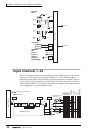
RETURN 1(...2)
Stereo in X 2
INPUT PATCH
INSERT
INSERT
METER METER
METER METER
METER
METER
AT T
AT T
BUS1
BUS2
BUS3
BUS4
BUS5
BUS6
BUS7
BUS8
STEREO L
STEREO R
SOLO L
SOLO R
AUX 1
AUX 6
AUX 7(EFF1)
AUX 8(EFF2)
PREFADER LISTEN/
AFTER PAN
SOLO
SOLO
PA N
PA N
PRE/POST
RETURN1 can not be assigned to AUX7
(EFF1)
RETURN2 can not be assigned to AUX8
(EFF2)
ON AUX
ON LEVEL
INPUT
DELAY
INPUT
DELAY
METER
4 BAND EQ
(EQ)
METER
4 BAND EQ
(EQ)
...