


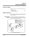

40 Using the Digitizers Chapter 2
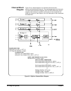
The trigger source from the master can be set with TRIG:SOURce1,2 IMM
| INT1-4 | EXT | TTLT<n>.
TRIG:MODE MASTer0 drives the TTL lines as if OUTPut:TTLT0:
SOURceSAMPle and OUTPut:TTLT1:SOURce TRIGger had been set.
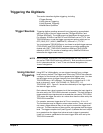
The master module generates the sample signal from which all modules
(master and slaves) initiate a measurement.
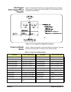
MASTer0 sets the TTLT1 line as if it were TRIG:SOUR1 TTLT1. However,
the query TRIG:SOUR? will not return this setting. This line is dedicated for
synchronization between the two modules in the master-slave mode. You
should not use this line for any other purpose with the OUTPut, SAMPle or
TRIGger commands.
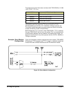
Example: Slave Module
Configuration
Figure 2-6 illustrates a module configured as a slave module. TRIG:MODE
SLAVe0 pairs TTLT0 (sample) with TTLT1 (trigger). A SLAVe0 module will
function with other SLAVe0 modules and with the MASTer0 module.
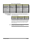
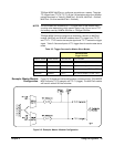
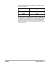
MODE MASTer Sample Signal
MASTer0 TTLT2-7 | INT1-4 | EXT
MASTer2 TTLT0,1,4-7 | INT1-4 | EXT
MASTer4 TTLT0-3,6-7 | INT1-4 | EXT
MASTer6 TTLT0-5 | INT1-4 | EXT
Figure 2-6. Slave Module Configuration