


20 Configuring the Digitizer Modules Chapter 1
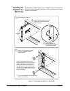
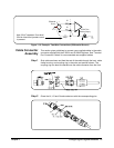
RAM Installation
Procedure
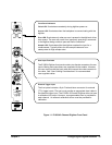
1 Disconnect any field wiring from the module and remove power from
the mainframe before proceeding.
2 Remove the module from the mainframe and remove the top shield
from the module.
3 Remove the 4 Mbyte SIMM from the PC board by first spreading the
tabs at the ends of the SIMM connector. Store this SIMM in an
anti-static bag and save this part.
NOTE It is important that you retain the 4 Mbyte SIMM you remove from the
Digitizer. If you return your Digitizer to Agilent for repair or exchange, you
must return it in the same configuration as it was shipped to you. You must
remove the large memory SIMM and replace it with the standard 4 Mbyte
SIMM shipped with the product.
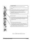
4 Add your replacement SIMM to the module’s RAM socket.
5 Reinstall the module’s top shield.
6 Note the new memory configuration by checking the appropriate box
on the module’s top shield.
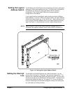
7 Set the “CALIBRATION CONSTANTS” switch and the “FLASH”
switch to the “Write Enable” position.
8 Install the module in the mainframe and apply power.
9 Set the new RAM memory size by sending
DIAGnostic:MEMory:SIZE <size>.
10 Query the memory size to verify the setting by sending
DIAGnostic:MEMory:SIZE?
11 Remove mainframe power, remove the module and set the
“CALIBRATION CONSTANTS” and “FLASH” switches back to the
“Read Only” position.
12 Reinstall the module in the mainframe.
WARNING TIGHTEN THE FACEPLATE SCREWS. Tighten the faceplate mounting
screws to prevent electric shock in case of equipment or field wiring
failure.