


14 Configuring the Digitizer Modules Chapter 1
All channels sample simultaneously. The sample can be from an internal
clock derived from the internal time base or it can come from an external
source. Triggering can be set up for several sources with programmable pre
and post trigger reading counts. External time base, trigger and sample
inputs are provided on the front panel “D” subminiature connector.
Continuous voltages in a test setup where the user has access to module
connectors and test signal cable ends are restricted to 60 Vdc, 30 Vac rms,
or 42.4 Vac peak of a continuous, complex waveform. Continuous voltages
in test setups where the module connectors and the test signal cables
connected to them are made non-accessible are 256 Vdc, 240 Vdc floating,
or 256 Vac peak.
Transient voltages are permitted providing the maximum amount of charge
transferred into a human body that contacts the voltage under normal
conditions, does not exceed 45
mCoulombs (45 mA-s). Overload voltages
(opens channel input relay) follow.
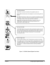
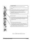
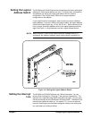
Front Panel
Features
Figure 1-1 shows the front panel features for the E1563A 2-Channel
Digitizer. Figure 1-2 shows the front panel features for the E1564A
4-Channel Digitizer.
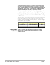
Range Voltage Input Condition Vmax
62 mV to 4V High or Low to Guard >20V
16V to 256V Low to Guard >40V