


Configuring the Digitizer Modules 27Chapter 1
Cable Connector
Assembly
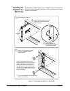
This section gives guidelines to connect user-supplied cables to the cable
connector supplied with the E1563A and E1564A Digitizers. See "Terminal
Port Connector Cables" for recommended user-supplied cables.
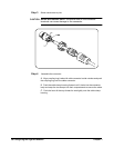
Step 1 Strip cable as shown and feed the end of the cable through the boot, cable
clamp housing, and coupling ring in the order and position shown. The
coupling ring can also be inserted onto the cable connector from the front.
Step 2 Orient the HI, LO and Guard conductors with the corresponding pins.
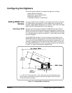
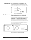
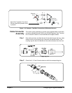
Figure 1-12. Example: Two-Wire Connections (Differential Source)
+
50
50
+
25 KHz From
Switching Supply
I Injected
100 pF
Differential
Source
Add 100 pF capacitor if low-level
25 kHz noise from injected current
is present.