


24 Configuring the Digitizer Modules Chapter 1
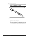
Trigger Input Port
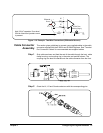
Cables
The user must supply a standard cable to the External Trigger Input port
(E1563A) or to the External Trigger Input/Calibration Bus Output port
(E1564A).
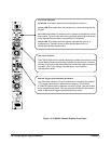
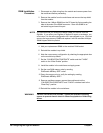
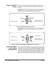
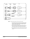
E1563A Digitizer. The E1563A front panel contains a 9-pin D-subminiature
connector with the pin-outs and associated SCPI commands shown in
Figure 1-6 (do not make any connections to the top two pins).
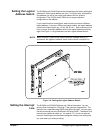
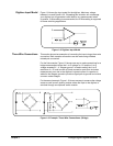
E1564A Digitizer. The E1564A front panel contains a 9-pin D-subminiature
connector with the pin-outs and associated SCPI commands shown in
Figure 1-7.
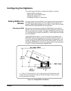
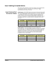
3-Wire and 2-Wire
Input Cabling
Considerations
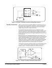
The E1563A and E1564A Digitizers provide a three-terminal input system
(High, Low and Guard) in which an unavoidable and undesirable current is
injected from chassis ground to the Guard terminal. Dependent on whether
you measure on a low-voltage range or a high-voltage range, the way you
connect the Guard terminal may or may not introduce a measurement error
due to this current. This section describes some considerations you can
take to use the Guard terminal properly to minimize measurement error.
Figure 1-6. E1563A External Trigger Input Port
SAMPle:SOURce EXT
TRIGger:SOURce EXT
ROSCillator:SOURce EXT
Figure 1-7. E1564A External Trigger Input/Calibration Bus Output Port
CAL:SOURce INT
SAMPle:SOURce EXT
CAL:SOURce INT
TRIGger:SOURce EXT
ROSCillator:SOURce EXT