


Using the Digitizers 39Chapter 2
TRIGger:MODE MASTer<n> configures a module as a master. The eight
TTL trigger lines (TTLT0-TTLT7) on the VXI backplane allow four different
pairings as shown in Table 2-2 (MASTer0 - SLAVe0, MASTer2 - SLAVe2,
MASTer4 - SLAVe4 and MASTer6 - SLAVe6).
NOTE You must select an unused set of TTL trigger lines for the master-slave
coupling when determining which master mode to set. Do not use a TTLT
line already used by SAMPle:SOURce or TRIGger:SOURce.
TRIGger:MODE SLAVe0 configures a module as a slave to a MASTer0
module. MASTer0 and SLAVe0 modules share TTL trigger lines TTLT0
and TTLT1. TTLT0 carries the sample signal and TTLT1 carries the trigger
signal. Table 2-2 shows all pairs of TTL trigger lines for each master-slave
mode.
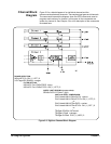
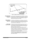
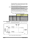
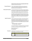
Example: Master Module
Configuration
Figure 2-5 illustrates a module configured as a master module. TRIG:MODE
MASTer0 pairs TTLT0 (sample) with TTLT1 (trigger). The MASTer0 module
will function with all SLAVe0 modules.
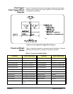
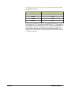
Table 2-2. Trigger Sources for Master-Slave Modes.
MASTer-SLAVe
Trigger Sources
MASTer MODE SLAVe MODE TRIG:SOUR1 TRIG:SOUR2
MASTer0 SLAVe0 TTLT1 Any source except TTLT0 & TTLT1
MASTer2 SLAVe2 TTLT3 Any source except TTLT2 & TTLT3
MASTer4 SLAVe4 TTLT5 Any source except TTLT4 & TTLT5
MASTer6 SLAVe6 TTLT7 Any source except TTLT6 & TTLT7
Figure 2-5. Example: Master Module Configuration