


Register-Based Programming 131Appendix B
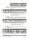
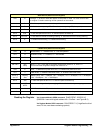
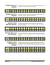
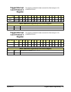
CVTable Channel 3
Register
This register holds the last value of the 2’s complement data stored in FIFO
for channel 3. Data is 14 bits with the LSB at bit 2.
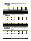
CVTable Channel 4
Register
This register holds the last value of the 2’s complement data stored in FIFO
for channel 4. Data is 14 bits with the LSB at bit 2.
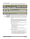
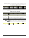
Samples Taken
High Byte Register
This register holds the upper 16 bits of the number of samples taken
(number of readings). The value in this register will continuously change
as readings are taken.
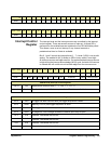
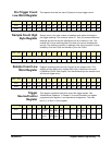
Samples Taken Low
Word Register
This register holds the lower 16 bits of the number of samples taken (number
of readings). The value in this register will continuously change as readings
are taken.
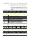
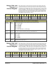
Calibration Flash
ROM Address
Register
This register holds the address of the calibration flash ROM that is used for
storing the calibration constants. Note the bit pattern 01010 for bits 15-11 in
the upper byte. A write to Flash ROM is aborted if this pattern is not present.
base + 14
16
15 14 13 12 11 10 9 8 7 6 5 4 3 2 1 0
Read MSB LSB 0 0
base + 16
16
15 14 13 12 11 10 9 8 7 6 5 4 3 2 1 0
Read MSB LSB 0 0
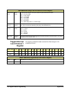
base + 18
16
15
(31)
14
(30)
13
(29)
12
(28)
11
(27)
10
(26)
9
(25)
8
(24)
7
(23)
6
(22)
5
(21)
4
(20)
3
(19)
2
(18)
1
(17)
0
(16)
Read 0000000000xxxxxx
base + 1A
16
15 14 13 12 11 10 9 8 7 6 5 4 3 2 1 0
Read xxxxxxxxxxxxxxxLSB
base + 1C
16
15 14 13 12 11 10 9 8 7 6 5 4 3 2 1 0
Write* 0 1 0 1 0A10A9A8A7A6A5A4A3A2A1A0
Read** 0 0 0 0 0A10A9A8A7A6A5A4A3A2A1A0