


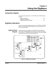
Using the Digitizers 35Chapter 2
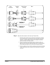
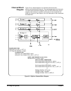
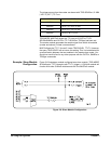
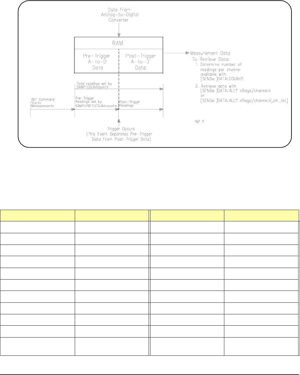
Pre-Trigger/
Post-Trigger Block
Diagram
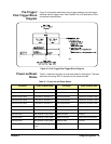
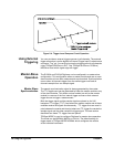
Figure 2-3 illustrates relationship of pre-trigger readings and post-trigger
readings with the trigger event. See Chapter 3 for a full description of the
commands illustrated here.
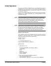
Power-on/Reset
States
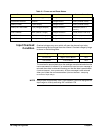
Table 2-1 describes all power-on and reset states for the digitizer. The reset
state after executing *RST is the same as the power-on state.
Figure 2-3. Pre-Trigger/Post-Trigger Block Diagram
Table 2-1. Power-on and Reset States.
Parameter Power-on/Reset State Parameter Power-on/Reset State
DIAG:INTerrupt:LINE interrupt line #1 VOLT4:RANGe 256V (channel 4 range)
FORMat:DATA ASCii VOLT1:RESolution 7.8125 mV (channel 1 res)
INPut1:FILTer:FREQ 0 (no filter on channel 1 ) VOLT2:RESolution 7.8125 mV (channel 2 res)
INPut2:FILTer:FREQ 0 (no filter on channel 2 ) VOLT3:RESolution 7.8125 mV (channel 3 res)
INPut3:FILTer:FREQ 0 (no filter on channel 3 ) VOLT4:RESolution 7.8125 mV (channel 4 res)
INPut4:FILT:FREQ 0 (no filter on channel 4 ) SAMPle:COUNt 1 (one sample)
INPut1:STATe ON (channel 1 input state) SAMPle:PRETrigger:COUNt 0 (no pretrigger samples)
INPut2:STATe ON (channel 2 input state) SAMPle:SLOPe POSitive
INPut3:STATe ON (channel 3 input state) SAMPle:SOURce TIMer (internal time base)
INPut4:STATe ON (channel 4 input state) SAMPle:TIMer 1.3 µsec
OUTPut:TTLT0-7:SOURce TRIGger (all TTLTrigger
lines)
TRIGger:LEVel1 -256V (channel 1 level)