


34 Using the Digitizers Chapter 2
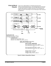
Channel Block
Diagram
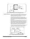
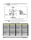
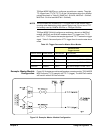
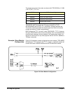
Figure 2-2 is a block diagram of an individual channel and the
interconnections between channels. The sample signal goes to all channels.
The commands beneath the diagram show the SCPI commands used to
program each section of a channel. In this case, all the commands are
written for channel 4. See Chapter 3 for a full description of the commands
illustrated here.
Figure 2-2. Digitizer Channel Block Diagram
RANGE SELECTION:
INPut4:STATe ON | 1 | OFF | 0
VOLTage4:DC:RANGe <range>
FILTER SETTING:
INPut4:FILTer:LPASs:FREQ <freq>
INPut4:FILTer:LPASs:STATe ON | 1 | OFF | 0
LIMIT and LEVEL COMPARISON:
CALCulate4:LIMit:LOWer:DATA <value>
CALCulate4:LIMit:LOWer:STATe ON | 1 | OFF | 0
or
CALCulate4:LIMit:UPPer:DATA <value>
CALCulate4:LIMit:UPPer:STATe ON | 1 | OFF | 0
or
TRIGger:SOURce INTernal4
TRIGger:LEVel4 <voltage>
TRIGger:SLOPe4 POS | 1 | NEG | 0
QUERY LAST READING (current value):
SENSe:DATA:CVTable? (@4)