


Configuring the Digitizer Modules 21Chapter 1
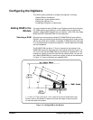
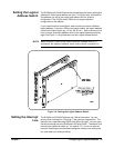
Setting the Logical
Address Switch
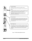
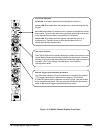
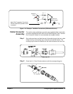
The E1563A and E1564A Digitizers are shipped from the factory with logical
address 40. Valid logical address are from 1 to 254 for static configuration
(the address you set on the switch) and address 255 for dynamic
configuration. The E1563A and E1564A do not support dynamic
configuration of the address.
If you install more than one digitizer, each module must have a different
logical address. If you use a VXIbus command module, the logical address
must be a multiple of eight (e.g., 32, 40, 48, 56, etc.). Each instrument must
have a unique secondary address which is the logical address divided by
eight. See Figure 1-4 for guidelines to set the Logical Address Switch.
NOTE When using an E1406A as the VXIbus resource manager with SCPI
commands, the digitizer’s address switch value must be a multiple of 8.
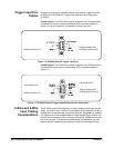
Setting the Interrupt
Line
The E1563A and E1564A Digitizers are VXIbus interrupters. You can
specify which interrupt line (1 through 7) the interrupt is transmitted. The
interrupt line is specified using DIAGnostic:INTerrupt:LINE. You can query
the active interrupt line using DIAGnostic:INTerrupt:LINE?. The default is no
interrupt line enabled at power-up. You specify “0” if you do not want an
interrupt. Resetting the module does change the interrupt line setting and
you must reset your interrupt setting.
Figure 1-4. Setting the Logical Address Switch