


156 Digitizers Verification Tests Appendix D
Gain Verification
Test
The gain verification tests check the positive and negative full scale gain on
each range for each channel. An external DCV source provides the input
and the digitizer’s "L" terminal is connected to the "G" terminal connecting
LO to GUARD. The input voltage is slightly less than full scale to avoid
overloading the range.
1 Set the digitizer as follows:
Reset the digitizer: *RST (sets FILT OFF)
Set channel 1 to the 62 mV range: VOLT1:RANG 62E-3
2 Set the DC Standard output to 55 mV.
3 Perform the measurement using the INITiate command. Retrieve the
reading using DATA? 1,(@1).
4 Verify the result is within specified limits and record the result.
5 Change ranges using VOLT<channel>:RANG <range> and make a
measurement for each DCV input and range shown in Table D-4,
verifying the result is within specified limits. Record the result.
6 Repeat step 5 for channel 2 on the E1563A 2-Channel Digitizer and
channels 2 through 4 on the E1564A 4-Channel Digitizer.
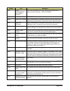
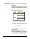
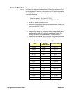
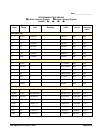
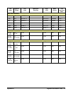
Table D-4. Gain Verification Test Points.
INPUT E1563A /
E1564A Range
Error from nominal
+55 mV 62 mV ± 38.7 mV
-55 mV 62 mV ± 38.7 mV
+0.24V 0.25V ± 160 mV
-0.24V 0.25V ± 160 mV
+0.95V 1 V ± 623 mV
-0.95V 1 V ± 623 mV
+3.8V 4 V ± 2.49 mV
-3.8V 4 V ± 2.49 mV
+15V 16 V ± 26.1 mV
-15V 16 V ± 26.1 mV
+60V 64 V ± 48.4 mV
-60V 64 V ± 48.4 mV
+100V 256 V ± 113 mV
-100V 256 V ± 113 mV