


132 Register-Based Programming Appendix B
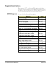
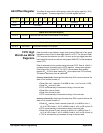
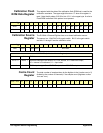
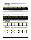
Calibration Flash
ROM Data Register
This register holds the data of the calibration flash ROM that is used for the
calibration constants. The upper eight bits return “0” when this register is
read. Note the bit pattern 01010 for bits 15-11 in the upper byte. A write to
Flash ROM is aborted if this pattern is not present.
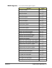
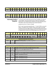
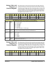
Calibration Source
Register
The E1564A 4-Channel Digitizer has an on-board calibration source.
The source is a 12-bit DAC with a gain switch. Bit 15 is the gain switch
and bits 11 through 0 are the calibration value.
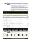
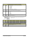
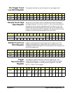
Cache Count
Register
The total number of samples taken by the digitizer is the ((cache count x 2)
divided by the number of channels) + the sample count (registers
at offset
18
16
and 1A
16
).
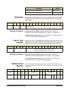
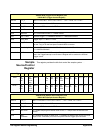
base + 1E
16
15 14 13 12 11 10 9 8 7 6 5 4 3 2 1 0
Write* 01010101D7D6D5D4D3D2D1D0
Read** 00000000D7D6D5D4D3D2D1D0
base + 20
16
15 14 13 12 11 10 9 8 7 6 5 4 3 2 1 0
Write
RANGE
MUX1 MUX0 DAC Data
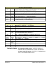
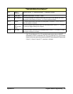
*WRITE BITS (Calibration Source Register)
bits 0-11 DAC
DAC data
bit 12, 13 MUX0, 1
connects choices to the output; 00 = CAL source, 01 = Raw DAC output,
10 = Internal +5V reference, 11 = Input short
bit 15 RANGE
DAC output ranges: 0 = ±15V DAC output, 1 = ±0.5V DAC output
base + 22
16
15 14 13 12 11 10 9 8 7 6 5 4 3 2 1 0
Write 00000000 Cache count