


36 Using the Digitizers Chapter 2
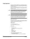
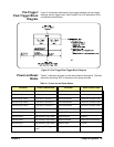
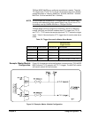
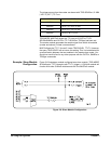
Input Overload
Condition
Overload voltages may occur which will open the channel input relay
disconnecting the input signal from the channel. Overload voltage by range
is shown in the following table.
The overload is reported both when the readings are retrieved and when the
next measurement is initiated. If an overload occurred, an error message is
returned when data is retrieved informing you that the data is questionable
(Overload detected - data questionable)
. An error message is also returned
when you initiate the next measurement
(Overload detected - attempting
re-connect of input relays).
NOTE Relays open at approxiately 260V. If this happens, you must reprogram the
input range to close by executing INP <channel> ON.
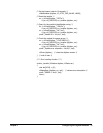
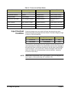
OUTPut:TTLT0-7:STATe OFF (all TTLTrigger lines) TRIGger:LEVel2 -256V (channel 2 level)
ROSCillator:SOURce INTernal TRIGger:LEVel3 -256V (channel 3 level)
SWEep:POINts 1 (one sample) TRIGger:LEVel4 -256V (channel 4 level)
SWEep:OFFSet:POINts 0 (no pretrigger samples) TRIGger:SOURce1 IMMediate (source 1
not ch 1)
VOLT1:RANGe 256V (channel 1 range) TRIGger:SOURce2 HOLD (source 2 not ch 2)
VOLT2:RANGe 256V (channel 2 range) TRIGger:SLOPe1 POSitive (slope 1 not ch 1)
VOLT3:RANGe 256V (channel 3 range) TRIGger:SLOPe2 POSitive (slope 2 not ch 2)
Table 2-1. Power-on and Reset States.
Parameter Power-on/Reset State Parameter Power-on/Reset State
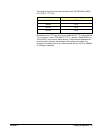
Range Voltage Input Condition Vmax
62 mV to 4V High or Low to Guard >20V
16V to 256V Low to Guard >40V