


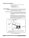

Configuring the Digitizer Modules 15Chapter 1
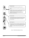
Figure 1-1. E1563A 2-Channel Digitizer Front Panel
plug&play
Front Panel Indicators
Failed LED: Illuminates momentarily during digitizer power-on.
Access LED: Illuminates when the backplane is communicating with the
digitizer.
Error LED: Illuminates only when an error is present in the digitizer’s driver
error queue. The error can result from improperly executing a command
or the digitizer being unable to pass self-test or calibration.
Sample LED: Illuminates while the digitizer samples the input for a
measurement. Typically blinks for slow sample rates and is on
steady-state for high sample rates.
User Input Terminals
The E1563A Digitizer front panel contains two female connectors for user
inputs. Mating male connectors are supplied with the module. However,
the user must provide the input cable and connect the male connector to
the cable. See "User Cabling Considerations" for recommended
user-supplied cables.
External Trigger Input
The front panel contains a 9-pin D-subminiature connector for external
(TTL) trigger inputs. The user must provide an appropriate input cable to
the external trigger input. The E1563A 2-Channel Digitizer does not have
a calibration bus output. However, a programmable short is provided for
each channel. An external calibration source must be provided for
calibration.