


Configuring the Digitizer Modules 25Chapter 1
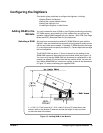
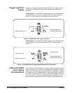
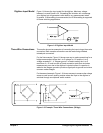
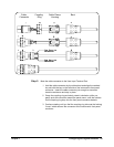
Digitizer Input Model Figure 1-8 shows the input model for the digitizer. Maximum voltage
between Low and Guard is 5V. Exceeding this limitation will not damage
your digitizer but will generate invalid data for any measurement taken.
In general, 3-Wire cabling is recommended, but 2-Wire cabling is supported
for some switching applications.
Three-Wire Connections This section shows two examples of connecting the input using a three-wire
connection. Both example connections can be made using shielded,
twisted-pair connectors.
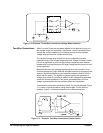
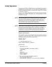
For the first example, Figure 1-9 shows one way to make connections for a
bridge measurement where the L-to-G voltage is £ 5V and the L-to-G
voltage exceeds 5V. A “Wagner ground” is used to satisfy the L-to-G
restriction of £ 5V and to make a Guard connection point that minimizes
measurement error due to the digitizer’s injected current. A capacitor is
added to the Wagner ground to provide a signal path to ground to minimize
common mode voltages.
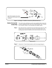
For the second example, Figure 1-10 shows one way to measure the voltage
across a small current sensing resistor where the input to the digitizer is
switched through a multiplexer switch module.
Figure 1-8. Digitizer Input Model
Figure 1-9. Example: Three-Wire Connections (Bridge)