


Register-Based Programming 129Appendix B
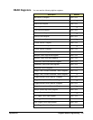
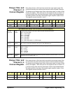
Interrupt Control
Register
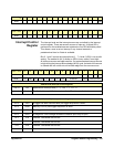
The interrupt level and the interrupt source are controlled by the interrupt
control register. There are several sources of interrupt. A logical OR is
performed on the enabled sources to determine if an IRQ should be pulled.
This allows a user to set an interrupt if any channel exceeds a
predetermined level or if data is available.
Bits 0, 1 and 2 control the interrupt level (1 - 7). Level 0 (000) is not a valid
setting. The enable bit (bit 3) allows an IRQ to occur when it is set high.
All interrupt sources are edge sensitive. If a masked latched interrupt source
is high during the interrupt acknowledge (IACK) cycle, the latch of the source
is cleared and will not be set until another edge from the source occurs. :
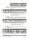
base + 08
16
15 14 13 12 11 10 9 8 7 6 5 4 3 2 1 0
Read LSB
base + 0A
16
15 14 13 12 11 10 9 8 7 6 5 4 3 2 1 0
Read LSB
base + 0C
16
15 14 13 12 11 10 9 8 7 6 5 4 3 2 1 0
Write* EnableL2L1L0
Read** TRIG DONE PRE OVER CH4 CH3 CH2 CH1 undefined Enable Interrupt Level
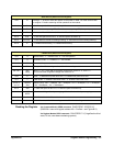
*WRITE BITS (Interrupt Control Register)
bits 0-2 L0-2
Specifies the interrupt level (1 - 7); “001” = 1, “111” = 7
bit 3 Enable
Enable the interrupt; “1” = interrupt enabled, “0” = interrupt disabled.
**READ BITS (Interrupt Control Register)
bit 15 TRIG
A trigger has been received after pre-trigger acquisition is done.
bit 14 DONE
Memory is full or post trigger acquisition is done.
bit 13 PRE
Pre-trigger data has been acquired.
bit 12 OVER
A dangerous OVERvoltage caused the channel input relay to open.
bit 11 CH4
Channel 4 exceeded the set limit.
bit 10 CH3
Channel 3 exceeded the set limit.
bit 9 CH2
Channel 2 exceeded the set limit.
bit 8 CH1
Channel 1 exceeded the set limit.