


Register-Based Programming 137Appendix B
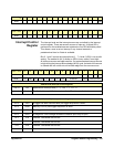
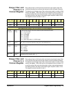
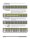
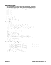
Pre-Trigger Count
Low Word Register
This register holds the low word (2 bytes) for the pre-trigger count.i
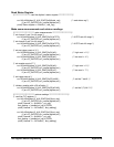
Sample Count High
Byte Register
Sample count is the total number of readings to be taken including the
pre-trigger readings. The minimum value is 1. Zero (0) causes continuous
readings and will not stop the acquisition until all of memory is full. The
module will not stop acquiring data if the host can remove readings fast
enough. The maximum number of readings is the size of memory in bytes
divided by 8 for the E1563 and divided by 4 for the E1564.
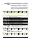
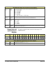
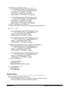
Sample Count Low
Word Register
Register containing the low word (2 bytes) for the sample count. This
register and the high byte in register 38
16
hold a value that can be set
by SAMPle:COUNt. See Chapter 2 for the relationship of the sample count
and the pre-trigger count.
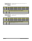
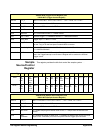
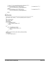
Trigger
Source/Control
Register
This register provides the bits that control the trigger system. See
“Master-Slave Operation” in Chapter 2 for more information on register
programming the digitizer in a master-slave configuration. This uses
bits 5, 6, 10 and 11 of the register.
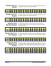
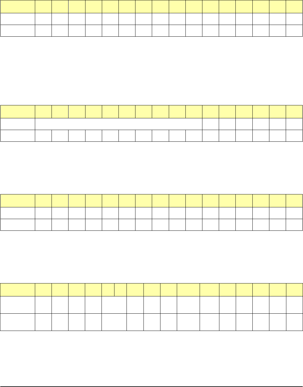
base + 36
16
15 14 13 12 11 10 9 8 7 6 5 4 3 2 1 0
Write C15C14C13C12C11C10C9C8C7C6C5C4C3C2C1C0
Read C15 C14 C13 C12 C11 C10 C9 C8 C7 C6 C5 C4 C3 C2 C1 C0
base + 38
16
15 14 13 12 11 10 9 8 7 6 5 4 3 2 1 0
Write undefined C5 C4 C3 C2 C1 C0
Read 0000000000C5C4C3C2C1C0
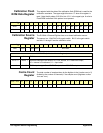
base + 3A
16
15 14 13 12 11 10 9 8 7 6 5 4 3 2 1 0
Write C15C14C13C12C11C10C9C8C7C6C5C4C3C2C1C0
Read C15 C14 C13 C12 C11 C10 C9 C8 C7 C6 C5 C4 C3 C2 C1 C0
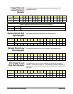
base + 3C
16
15 14 13 12 11 10 9 8 7 6 5 4 3 2 1 0
Write*
CMP4 CMP3 CMP2 CMP1 SLAVING
PAIR
EX_
TRIG
POS_
NEG
SOFT
TRIG
MASTER SLAVE EN_
TTL
IN/
OUT
TTL_3 TTL_1 TTL_0
Read**
CMP4 CMP3 CMP2 CMP1 SLAVING
PAIR
EX_
TRIG
POS_
NEG
SOFT
TRIG
MASTER SLAVE EN_
TTL
IN/
OUT
TTL_3 TTL_1 TTL_0