


Configuring the Digitizer Modules 23Chapter 1
User Cabling Considerations
This section gives guidelines to select and configure user-supplied cables
for connection to the Input Terminals and to the External Trigger
Input/Calibration Bus Output Terminals.
Input Terminal Port
Connector Cables
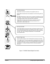
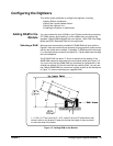
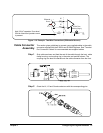
E1563A Digitizer. The E1563A Digitizer front panel includes two Switchcraft®
EN3™ Mini Weathertight Connectors (female) (CH-1 and CH-2). See Figure
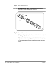
1-1. Mating Switchcraft® Cord Connectors (male) are supplied with the
module. However, the user must provide the cable and assemble the
connector to the cable end. Recommended shielded, twisted-pair cable in
the following table have an outside dimension compatible with the cord
connector.
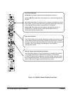
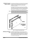
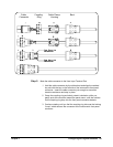
E1564A Digitizer. The E1564A Digitizer front panel contains four
Switchcraft® EN3™ Mini Weathertight Connectors (female) (CH-1 through
CH-4). See Figure 1-2. Mating Switchcraft® Cord Connectors (male) are
supplied with the module. However, the user must provide the cable and
assemble the connector to the cable end. Recommended shielded,
twisted-pair cable in the following table have an outside dimension
compatible with the cord connector.
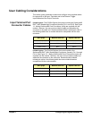
Wire gauge Belden® cable P/N Alpha® cable P/N
20 AWG (7x28) 8762 none
22 AWG (7x30) 9462 5481C
24 AWG (7x32) 8641 5491C
Wire gauge Belden® cable P/N Alpha® cable P/N
20 AWG (7x28) 8762 none
22 AWG (7x30) 9462 5481C
24 AWG (7x32) 8641 5491C