


38 Using the Digitizers Chapter 2
Using External
Triggering
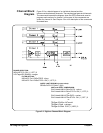
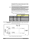
You can provide an external trigger common to all channels. The external
trigger connection is on the digitizer’s External Trigger Input D-subminiature
connector “Trig” pin. You set this input as the trigger source for all channels
using TRIGger:SOURce<n> EXT. Use TRIGger:SLOPe<n> POSitive |
NEGative to set which signal edge will trigger.
Master-Slave
Operation
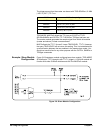
The E1563A and E1564A Digitizers can be configured in a master-slave
configuration. This configuration allows a master module and one or more
slave modules to have their measurements synchronized. Synchronization
occurs when all channels trigger from the same trigger event and all
channels sample from one sample signal.
Master-Slave
Synchronization
The sample synchronization signal is always generated by the master.
The TTL trigger event can be generated by either the master module or any
of the slave modules. This allows a slave module (as well as the master
module) to use one of the four internal trigger sources or their external
trigger source to trigger a measurement.
Both the trigger signal and the sample signal are placed on the VXI
backplane TTL trigger (TTLT) lines where the master module and all slave
modules receive the signals simultaneously. TTL trigger lines are used in
pairs between the master and slave(s) where one TTL trigger line carries the
sample signal and the other carries the trigger signal. The next section
describes how these TTL trigger lines are paired.
TRIGger:MODE is used to configure Digitizers for master-slave operation.
The mode can be NORMal, MASTer or SLAVe. The default setting for
trigger mode is TRIGger:MODE NORMal which configures the module
as an individual instrument.
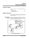
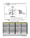
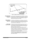
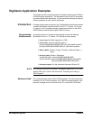
Figure 2-4. Trigger Level Compare Circuit Operation