


26 Configuring the Digitizer Modules Chapter 1
.
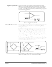
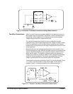
Two-Wire Connections When Low and Guard are connected together at the digitizer’s input on a
low-voltage range (4V and below), the injected current is directed to flow
through the source impedance (in a floating source) and the resultant
voltage drop will introduce a measurement error.
The resultant voltage drop through the source impedance can be a
significant error on low-voltage ranges where the voltage of interest is small.
It is not as significant an error on high-voltage ranges because the error
introduced is not a significant part of a larger voltage and the percent of error
is less significant.
Measurement error can increase significantly when you connect Low to
Guard at the digitizer’s input AND use switches to switch input signals to the
digitizer. Some switches have input protection resistors (usually 100W) in
series with the switch. The digitizer’s injected current now generates a
voltage drop across this resistor in addition to the voltage drop generated
across the source impedance. Even with a grounded source, an error
voltage is generated across the switches current limiting resistor.
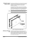
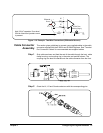
Two examples of two-wire connections follow. For the first example, Figure
1-11 shows a typical connection using coaxial cable. For the second
example, Figure 1-12 shows connections for a differential source.
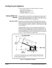
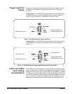
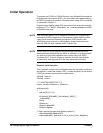
Figure 1-10. Example: Three-Wire Connections (Voltage Measurements)
Figure 1-11. Example: Two-Wire Connections (Coaxial Cable)