


Configuring the Digitizer Modules 19Chapter 1
Configuring the Digitizers
This section gives guidelines to configure the digitizers, including:
• Adding RAM to the Module
• Setting the Logical Address Switch
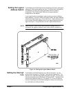
• Setting the Interrupt Line
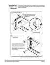
• Installing the Digitizer in a Mainframe
Adding RAM to the
Module
You can increase the size of RAM on your Digitizer module by purchasing
PC SIMM memory and installing it on the module after you remove the
standard 4 Mbyte SIMM shipped with your digitizer. Both FPM (Fast Page
Mode) and EDO (Extended Data Out) are supported.
Selecting a RAM Although most commercially available PC SIMM RAM will work with the
Digitizer, there are some that are physically too large and will make contact
with the top shield when installed. A standard 72 SIMM specifies the length
(L) or keying but does not specify the depth (D). Certain depths are too large
and not compatible.
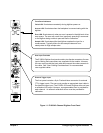
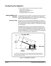
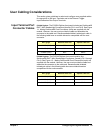
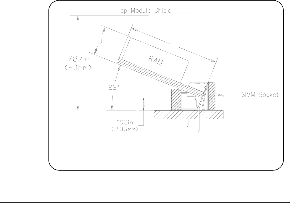
The E1563/E1564 has about 17.6 mm of space from the bottom of the
SIMM RAM inserted in the socket to the top module shield (see Figure 1-3).
You must verify that the SIMM RAM you purchase for replacement on the
module has a depth (D) that will clear the top module shield. You can use
the 4 Mbyte SIMM RAM you remove as a guide, as well as the dimensions
in Figure 1-3, when purchasing your upgrade RAM .
Figure 1-3. Adding RAM to the Module
L = 1.25in (31.77mm) max for D = 0.18, where D is from PC board lower side
where it rests on the bracket. D does not include the height of chips mounted
on the lower side of the board.