


134 Register-Based Programming Appendix B
:
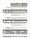
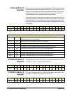
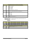
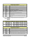
Trigger/Interrupt
Level Channel 1
Register
This register provides 8-bit data corrected for offset and gain in 2’s
complement format. :
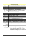
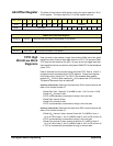
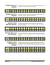
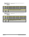
WRITE/READ BITS (Range, Filter and Channel 3/4 Connect Register)
bits 0-2 and
8-10
Gain
Code
These bits set the gain of the input channel by the codes shown below:
000 = 62.5 mV range
001 = 0.25V range
010 = 1.0V range
011 = 4.0V range
100 = 16V range
101 = 64V range
110 = 256V range (also 111 = 256V range)
bits 3
and 11
short3,
short4
These bits connect an internal short to the channel inputs when the bit is “1”. When it is “0”,
bits 7 & 15 connect the channel to the input or the calibration bus.
bits 4-6 and
12-14
Filter
Code
These bits set the input channel filter cut-off frequency by the codes shown below:
000 = 1.5 kHz
001 = 6 kHz
010 = 25 kHz
011 = 100 kHz
111 = NO filter
bits 7 and
15
Connect
Code
This bit connects the input channel to the front panel connector (Connect Code = 0) or to the
calibration bus (Connect Code = 1).
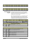
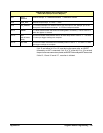
base + 28
16
15 14 13 12 11 10 9 8 7 6 5 4 3 2 1 0
Write*MSB-D7D6D5D4D3D2D1D00000000GL
Read**MSB-D7D6D5D4D3D2D1D00000000GL
*WRITE/**READ BITS (Trigger/Interrupt Level Channel 1 Register)
bit 0 GL Greater than or Less than; “0” = >, “1” = <.
bits 15-8 D7-D0 data bits.