


128 Register-Based Programming Appendix B
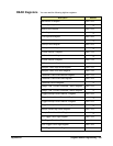
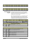
A24 Offset Register The offset of the module in A24 space is set by the upper eight bits (15-8)
of this register. The lower eight bits (7-0) of this register are zero.
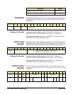
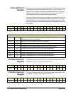
FIFO High
Word/Low Word
Registers
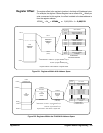
Data is stored on the module in large, slow dynamic RAM and in fast, small
backplane cache. Each of these data stores is a FIFO. The dynamic RAM
FIFO receives the data from the ADC. As soon as the pre-trigger data has
been identified, data is moved from the dynamic RAM FIFO to the backplane
cache FIFO.
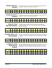
Data is removed from the module using the cache FIFO. Data is 16-bit 2’s
complement and is packed into the FIFO registers. Always read register
08
16
before 0A
16
if using D16. The FIFO is incremented after reading
register 0E
16
. If D32 is used, reading 08
16
will increment the FIFO correctly.
The data is interwoven from all channels.
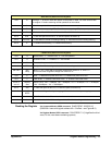
Ordering of Data (D16): Ordering of the data when D16 is used to remove the
data on a 4-channel module is:
• Read 08
16
chan 1 data (bit 15 is MSB of chan 1, bit 0 is chan 1 LSB)
• Read 0A
16
channel 2 data
• FIFO is automatically incremented to bring in the next data
• Read 08
16
channel 3 data
• Read 0A
16
channel 4 data
• FIFO is automatically incremented to bring in the next data
Ordering of Data (D32): Ordering of the data when D32 is used to remove the
data on a 4-channel module is:
• Read 08
16
channel 1 data, channel 2 data (bit 31 is MSB of chan 1,
bit 16 is LSB of chan 1, bit 15 is MSB of chan 2, bit 0 is LSB of chan 2)
• FIFO is automatically incremented to bring in the next data
• Read 0A
16
channel 3 data, channel 4 data (bit 31 is MSB of chan 3,
bit 16 is LSB of chan 3, bit 15 is MSB of chan 4, bit 0 is LSB of chan 4)
• FIFO is automatically incremented to bring in the next data
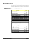
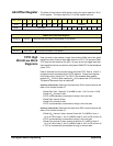
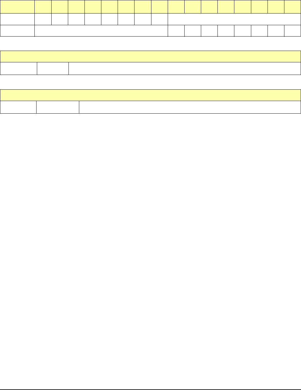
base + 06
16
15 14 13 12 11 10 9 8 7 6 5 4 3 2 1 0
Write* A23 A22 A21 A20 A19 A18 A17 A16 undefined
Read** A24 Offset 00000000
*WRITE BITS (A24 Offset Register)
bits 8-15 A16-A23
These bits set the offset of the module in A24 space.
**READ BITS (A24 Offset Register)
bits 8-15 A24 Offset
The module’s offset in A24 space.