


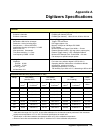

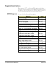
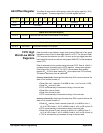

Register-Based Programming 127Appendix B
:
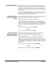
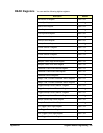
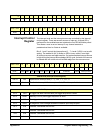
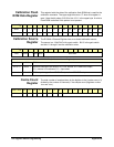
Reading the Register Via Command Module PEEK command: DIAG:PEEK? 2083332,16
(2083328 = base with logical address 40 + 04 offset - see Figure B-2)
Via Digitizer Module PEEK command: DIAG:PEEK? 2 (2 signifies the third
word, 16 bits, zero-base numbering system)
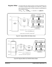
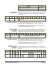
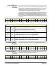
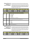
*WRITE BITS (Status/Control Register)
bit 0 R Writing a "1" to this bit resets the digitizer to the power-on state. You must set bit 0 back
to a logical "0" before resuming normal operations of the module.
bit 1 S “1” inhibits sysfail, “0” does not inhibit sysfail.
bit 6 E “1” disables error reporting LED, “0” enables error reporting LED (front panel).
bit 7 F “1” disables Flash ROM “write”, “0” enables Flash ROM “write”.
bit 12 A24 “1” sets A24 space as all FIFO, “0” sets A24 space as broken up.
bit 13
MOT-INTEL
“1” sets Motorola format for reading ordering, “0” sets Intel format for reading ordering.
bit 15 A “1” enables A32 decoding, “0” enables A24 decoding.
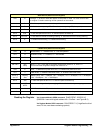
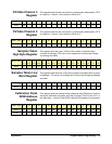
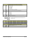
**READ BITS (Status/Control Register)
bit 0 R Reset Status; "1" = module reset, "0" = normal operation.
bit 1 S SYSFAIL inhibit; “1” = inhibited, “0” = not inhibited.
bit 2 P Passed; “1” = passed, “0” = failed.
bit 3 RDY Ready; “1” = A32 decoding enabled, “0” = A24 decoding enabled.
bits 4 & 5 Arm
Delay
Bit 4 is “1” for 1 msec after a range/filter change then returns to “0”, bit 5 is “1”
for 30 msec after range/filter change then returns to “0”.
bit 6 E Error; “1” disables front panel error LED, “0” enables front panel error LED.
bit 7 F Flash ROM; “1” disables Flash ROM “write”, “0” enables Flash ROM “write”.
bits 8, 9,
and 10
Memory
Size
Memory Size; “000” = 4 MBytes, “001” = 8 MBytes, “010” = 16 MBytes, “011” = 32 MBytes,
“100” = 64 MBytes, “101” = 128 MBytes.
bit 12 A24 “1” sets A24 space as all FIFO, “0” sets A24 space as broken up.
bit 13 MOT-
INTEL
“1” = Motorola big endian byte swapping, “0” = Intel little endian byte swapping.
bit 14 M MODID bit; if the bit is "0", module has been selected.
bit 15 A A24/A32 enable; “1” = A32 decoding enabled, “0” = A24 decoding enabled.