


Acquiring Waveforms
3-6
CSA8000B & TDS8000B User Manual
CAUTION. Install sampling modules before applying power and before connect-
ing them to the signals you want to test. See your sampling-module user manual
for instructions.
CAUTION. Sampling modules are inherently vulnerable to static damage. Always
observe static-safe procedures and cautions as outlined in your sampling-module
user manual.
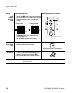
Coupling Concerns. Electrical sampling modules provide only straight-DC
coupling to their sampling circuits, with no protection. All modules specify a
maximum vertical nondestructive range that limits signals to small levels,
typically about 2 to 3 volts (DC + AC
pk-pk
). (See Specifications in the user
manual for your sampling module for exact limits.) Do not exceed the limit, even
momentarily, as the input channel may be damaged.
All modules also specify a dynamic range that, if exceeded, could cause
acquisition and measurement errors due to nonlinearity. Do not exceed this limit.
(See Specifications in the user manual for your sampling module for exact
limits.)
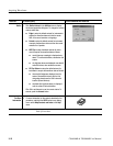
NOTE. Optical sampling modules may have dynamic range exceeded without
obvious visual indications onscreen because the photo detector and/or filters
used may not necessarily be able to pass through overloaded signals to the
sampler.
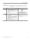
Use external attenuators if necessary to prevent exceeding the limits just
described. Note that there are no hardware bandwidth filters in most sampling
modules or in the instrument. (S ome optical sampling modules have bandwidth
filters settable from the Vertical Setup menu of the instrument. See the user
manual for your optical sampling module for more information.)
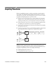
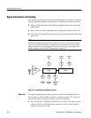
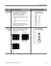
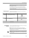
Scaling, Offset, and Positioning Considerations. These key controls determine the
portion of the input signal presented to the acquisition system:
H Set the vertic a l off set to display the featur es of interest on your wavef orm
and avoid clipping. (See Note that follows.) Adjust the display control
Ver tica l Scale to contr ol the portion of the ver tica l window displayed on
scre e n; adjust the display control Vertic al Position to position the wave for m
on screen. Note that vertic a l off set af f ec ts the ver tica l acquisition window,
but vertical scale and position do not. These last two controls are display
controls only. Vertic al Acquisition Window Conside rations on page 3--14
descr ibe s the ver tica l acquisition window.