


Incoming Inspection
1-26
CSA8000B & TDS8000B User Manual
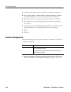
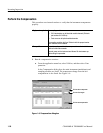
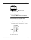
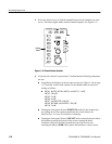
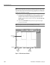
3. Select the channel to test: Push the channel button for the channel you want
to test. The button lights amber and the channel displays. See Figure 1--9.
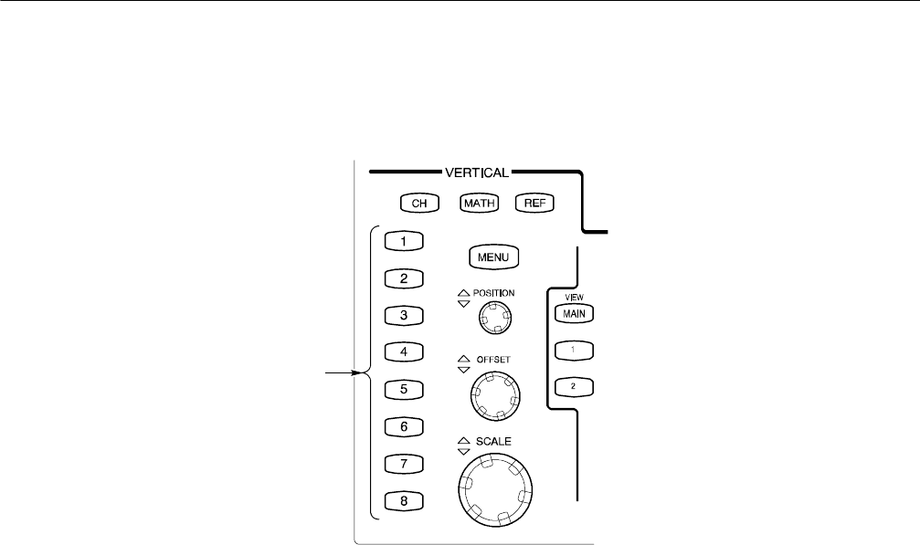
Channel
buttons
Figure 1- 9: Channel button location
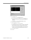
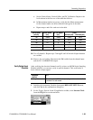
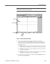
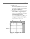
4. Verify that the channel is operational: Confirm that the following statements
are true.
H A baseline trace displays at about center screen (see F igure 1 --10 on page
1--27) and the vertical scale readout for the channel under test shows a
setting as follows:
H 80C01, 80C02, 80C04, 80C09, and 80C11: 1 mW
80C03: 100 W
80C05: 3 mW
80C06: 6 mW
80C07, and 80C07B: 100 W
80C08, 80C08B, and 80C08C: 200 W
80C10: 3 mW
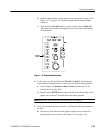
H Turning the front-panel Vertical POSITION knob (for the channel you
are testing) moves the signal up and down the screen. Return the
baseline trace to center screen before continuing.
H Turning the front-panel Vertical OFFSET knob counterclockwise offsets
the baseline towards the bottom of the screen; turning the knob
clockwise offsets the baseline towards the top of the screen, and
returning the knob to 0.000 offset returns the baseline to center screen.