


Appendix B: Automatic Measurements Reference
B-2
CSA8000B & TDS8000B User Manual
Pulse Measurements - Amplitude
Table B--1 describes on page B--2 describes each pulse measurement in the
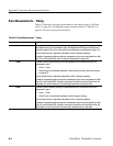
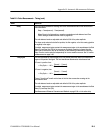
amplitude category. See Table B--2 on page B--8 for timing category measure-
ments; see Table B--3 on page B--14 for area category measurements.
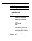
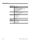
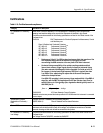
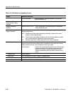
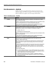
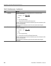
Table B- 1: Pulse Measurements — Amplitude
Name Definition
AC RMS The root-mean-square voltage, minus the DC component, of the waveform that is sampled
within t he measurem ent regi on.
If enabled, measurement gates constrain the measurement region to the area between the Start
Gate (G1) and Stop Gate (G2). See To Localize a Measurement on page 3--83.
For best results with this measurement, optimize the vertical resolution before taking this
measurement. See To Optimize the Vertical Resolution on page B--69.
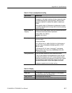
Amplitude The vert ical difference between the High and Low of the signal. The method used to determine
the High and the Low values can be controlled independently by the tracking method. See
Tracking Methods on page B--66. Also see High/Low Tracking Method on page 3--77.
Amplitude = High – Low
Where High and Low are measured values.
If enabled, measurement gates constrain the measurement region to the area between the Start
Gate (G1) and Stop Gate (G2).
For best results with this measurement, optimize the vertical resolution before taking this
measurement. See To Optimize the Vertical Resolution on page B--69.
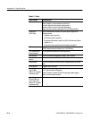
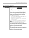
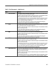
Average Optical Power
(dBm)
The true average component of an optical signal, expressed in decibels. This measurement
results from the use of a hardware average-power monitor circuit rather than from the
calculation of digiti zed waveform dat a.
Note: Average optical power measurements return valid results only on channels that contain
average power monitors. In general, all optical sampling module channels contain average
power monitors.
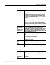
To determi ne Average Opti cal Power (dBm), this measurement simply converts average optical
power (watt s) to decibel s using a log10 function, referenced to 1 mW. To see how average
optical power in watts is determined, see the Average Optical Power (Watts) measurement on
the following page.
For best measurement results:
H Use a factory-calibrated wavelength. If using the USER wavelength setting, ensure that it
is properly compensated by performing the User Wavelength Gain compensation found by
clicking the Optical button in the Vertical Setup dialog box.
H Compensate the opt ical channel (found in the Utilities -- >Compensation dialog box). A
portion of this overall opt ical channel compensati on wi ll correct for minor DC variances in
the average power monitor.