


Appendix A: Specifications
CSA8000B & TDS8000B User Manual
A-9
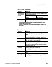
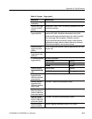
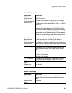
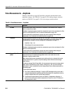
Table A- 7: Ports (cont.)
Specifications Characteristics
Gated Trigger Input --
Enable-to-Acquire
Delay
(Option GT equipped
instruments onl y)
3 trigger cycles, where each cycl e is def ined as (holdoff time + trigger
latency). For example:
With holdoff set to its minimum 5 s setting, and a 2.500 GHz clock
signal applied to the External Di rect Trigger input (a period of 400 ps),
the Enable-to-Acquire delay is approximated as 3 x (5 s + 0.0004 s)
= 15.0012 s.
The Enable-to-Acquire delay is the amount of time after the Gated
Trigger has been enabled (the level goes from TTL LOW to HIGH)
when the first val id sample is retai ned by the system as the beginni ng
of the waveform record length. When the Gated Trigger is enabled and
triggers begin to occur, t he system will reject the fi rst t hree samples t o
avoid system recovery conditions. Once the first three points have been
discarded, then the next vali d tri gger cycle will be the f irst point of the
record section.
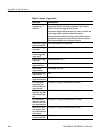
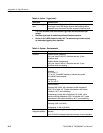
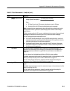
Gated Trigger Input --
Maximum Disable
Time
(Option GT equipped
instruments onl y)
The system checks t he status of t he gated Trigger approximately once
per holdoff and re-arm cycle. If the Gated Trigger is disabled
immediately af ter thi s system check, it will allow nominally a maximum
time of (holdoff + trigger period) to elapsed before the checking for the
status of the Gated Trigger input, recognizing the disable condition, and
halting any further sampling of the signal.
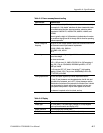
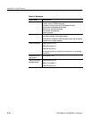
Internal clock t rigger
out
Square wave out from 50 Ω. back termination synchronized to t he
TDR internal clock drive signal . R efer to Trigger System -- Internal
Clock.
Typical performance into 50
Ω termi nation:
--0.20 to +0.20 V low level
+0.90 to +1.10 V high level
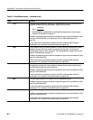
n DC calibration
output
DC voltage from l ow impedance drive, programmabl e t o 1 mV over
±1.25 V range maximum. Accuracy is 0. 2 mV + 0.1% i nto 50
Ω.
DC calibration output ,
typical
Typical Accuracy is 0.2 mV + 0.1% into 50 Ω.
External 10 MHz
reference i nput
±5 V maximum
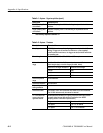
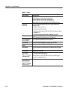
Table A- 8: Data storage
Specifications Characteristics
Floppy disk drive 3.5 in floppy disk, 1.44 Mbyte, compatable with DOS 3.3, or later,
format for storing reference waveforms, image files, and instrument
setups.
Hard disk drive ca-
pacity
≥ 20 Gbytes