


Incoming Inspection
CSA8000B & TDS8000B User Manual
1-25
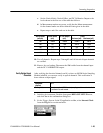
c. Set the Vertical Scale, Vertical Offset, and DC Calibration Output to the
levels shown in the first row of the table that follows.
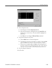
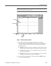
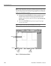
d. In Measurement readout on screen, verify that the Mean measurement
for the channel under test falls within the limits given in the table.
e. Repeat steps c and d for each row in the table.
Vertical Scale Vertical Offset DC CAL Output Limits
(mV/div) (mV) (mV) Minimum (mV) Maximum (mV)
100
--1000.0 --1000.0 --1009.0 --991.0
100 0.0 --450 --461.0 --439.0
100 0.0 0 -- 2 .0 2. 0
100 0.0 450 439.0 461.0
100 1000.0 1000.0 991.0 1009.0
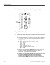
10. Test all channels: Repeat steps 3 through 9 until all electrical input channels
are verified.
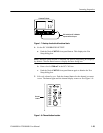
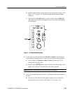
11. Remove the test hookup: Disconnect the SMA cable from the channel input
and the DC CALIBRATION output.
After verifying the electrical channels and if you have an 80C00 Series Sampling
Module installed, you can now verify its optical channels. This verification is
done without an input signal.
Equipment
required
None.
Prerequisites At least one optic al (80C00 series) sam pling module must be i nstalled
as outlined in its user manual.
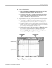
1. Initialize the instrument: Push the front-panel DEFAULT SETUP button,
and click Yes in the confirmation dialog box.
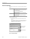
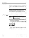
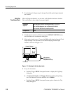
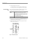
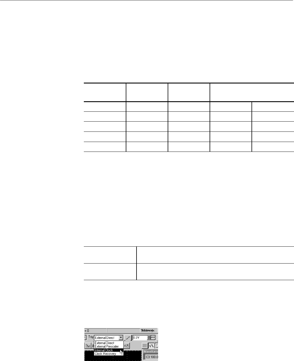
2. Set the Trigger System: In the UI application toolbar, select Internal Clock
from the Trig list box as shown below.
Verify Optical Input
Channels