


Incoming Inspection
CSA8000B & TDS8000B User Manual
1-33
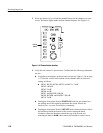
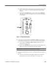
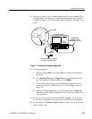
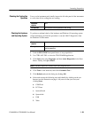
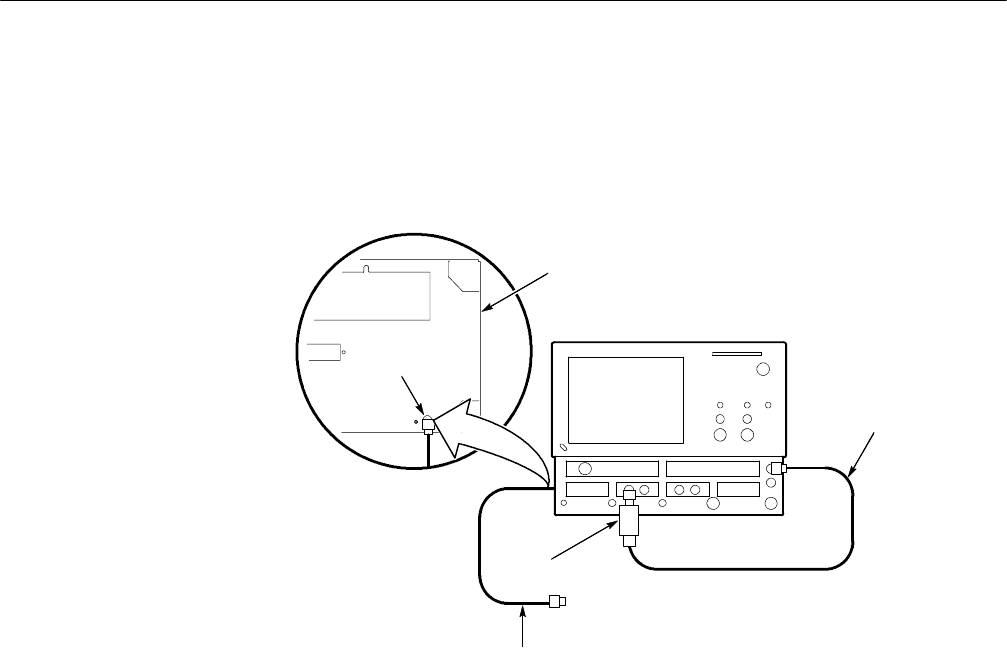
3. Hook up the signal source: Connect the SMA cable from the Internal Clock
output through a 10x attenuator to 80E00 sampling module input channel 3
as shown in Figure 1--16. Connect BNC cable to External Gate input at rear
panel.
CSA8000/TDS8000
SMA cable from
INTERNAL CLOCK
outputto 80E00 C3input
10x attenuator
BNC cableattached to TRIGGER
GATE (TTL) onthe rear panel.
TRIGGER
GATE (TTL)
Rear panel
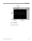
Figure 1- 16: Hookup for the gated trigger tests
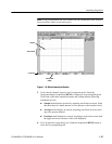
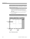
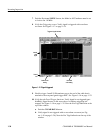
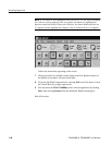
4. Set up the instrument:
a. Push the Trigger MENU front-panel button to display the Trig Setup
dialog box.
b. Click Internal Clock under Trigger Source in the Trig Setup dialog
box. The Internal C lock rate should be set to 200kHz.
c. Verify that the Gated Trigger option in Enhanced Triggering section is
selected (check box is checked). See To Use Gated Trigger,step4on
page 3--51.
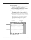
d. Turn the Vertical SCALE knob to set the vertical scale to 50 mV/div.
The channel scale readout is displayed in the Control bar at the bottom
of the graticule.
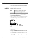
5. Set the time base: Set the Horizontal SCALE to 2 s/div. The horizontal
scale readout is displayed in the Control bar at the bottom of the graticule.
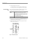
6. Set the display for Normal and Show Vectors (enable). See To Set Display
Styles on page 3--68.