


Appendix B: Automatic Measurements Reference
CSA8000B & TDS8000B User Manual
B-49
Table B- 7: NRZ Measurements - Amplitude (cont.)
Name Definition
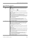
NRZ RMS Noise One standard deviat ion of the amplitude variance sampled wit hin a fi xed width verti cal slice
located at the center of the Eye Aperture at the High (logical 1) or Low (logical 0) levels.
RMS noise = Highσ or RMS noise = Lowσ
The Eye Aperture is adj ustable and defaults to 20% of the NRZ bit time. The High or Low
selection for Noise At control in the Measurement Setup dialog instructs the measurement to be
performed on the logical 1 or 0 l evels. See RZ Eye Aperture Parameters on B--62.
If enabled, measurement gates constrain the measurement region to the area between the Start
Gate (G1) and Stop Gate (G2). See To Localize a Measurement on page 3--83.
This measurement requires the use of a waveform database. When this measurement is turned
on, it will automat ically set the measurement system to use a waveform database if available.
See Use a Waveform Database on page B--70.
For best result s with t his measurement:
H Perform a Dark Level compensati on before taki ng this m easurement if the source of the
measured waveform is an optical channel. See To Perform Dark-Level and User
Wavelength Gain Compensations on page 3--98.
H Optimize the vertical resolution before taking this measurement. See How to Optimize the
Vertical Resolution on page B--70.
NRZ Signal-to-Noise
Ratio
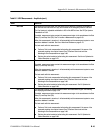
NRZ Signal-to-Noise is the ratio of the NRZ eye amplitude to the noise on either the High
(logical 1) or Low (logical 0) level. The data within the Eye Aperture is sampled, and the mean
of the hist ogram yi elds the High and Low levels. The noise is defined as one standard deviation
of the dist ri bution within a fixed width vertical slice located at the center of the Eye Aperture.
Where High and Low are the logical 1 and 0 levels. See RZ Eye Aperture Parameters
on B--62.
The Eye Aperture is adj ustable and defaults to 20% of the NRZ bit time. The High or Low
selection for Noise At control in the Measurement Setup dialog specifies that the measurement
be performed on the logical 1 or 0 levels. See To Localize a Measurement on page 3--83.
If enabled, measurement gates constrain the measurement region to the area between the Start
Gate (G1) and Stop Gate (G2).
This measurement requires the use of a waveform database. When this measurement is turned
on, it will automat ically set the measurement system to use a waveform database if available.
See Use a Waveform Database on page B--70.
For best result s with t his measurement, perform a Dark Level compensation before taking this
measurement i f the source of the measured waveform is an optical channel. See To Perform
Dark-Level and User Wavelengt h Gain Compensations on page 3-- 98.
SፒNRatio=
(High − Low)
Highσ
or SፒNRatio=
(High − Low)
Lowσ