


Acquiring Waveforms
3-28
CSA8000B & TDS8000B User Manual
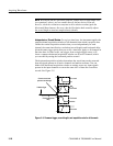
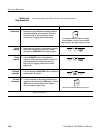
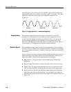
repeated trigger events, also provides the digitized signal data from which the
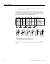
instrument assembles the waveform record (see Figure 3--9 on page 3--29). The
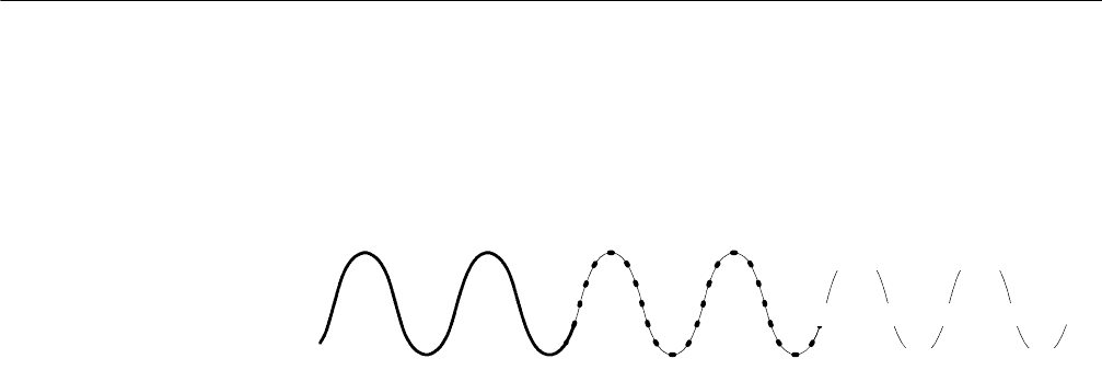
signal parts within the vertical range of the sampler are digitized. See
Figure 3--8.
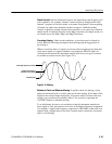
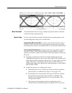
Inputsignal Sampled points Digital values
+0.5V
-- 0. 5 V
+0.5V
-- 0. 5 V
0V 0V 0V 0V
Figure 3- 8: Digital acquisition — sampling and digitizing
The instrument acquisition system can process the data as it is acquired,
averaging or enveloping the waveform data to produce enhanced waveform
records. Once the waveform record exists (enhanced or not), you can use the
post-processing capabilities of the instrument to further process that record:
perform measurements, waveform math, mask tests, and so on. Refer to Keys to
Using on page 3--22 for description of all three acquisition modes.
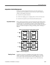
While sampling the input signal provides the data that makes up the waveform
record for any given channel, the instrument builds the waveform record through
use of some common parameters (“common” means they af fect the waveforms in
all channels).
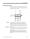
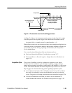
Figure 3--9 shows how these common parameters define the waveform record; as
shown in the figure, they define where in the data stream data is taken and how
much data is taken. Locate the following parameters in the figure:
H Sample Interval. The precise time between sample points taken during
acquisition.
H Record Length. The number of samples required to fill a waveform record.
H Trigger Point. The trigger point marks the time zero in a waveform record.
All waveform samples are located in time with respect to the trigger point.
H Horizontal Delay. The time lapse from the trigger point to the first sample
taken (first point in the waveform record). It is set indirectly by setting the
horizontal position (see Horizontal Position and the Horizontal Reference on
page 3--59).
Sampling Modes
Waveform Record