


System Overview Maps
CSA8000B & TDS8000B User Manual
2-5
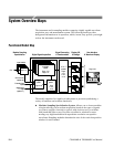
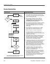
H Digital Signal Acquisition System. Acquires a waveform record from each
signal you apply to each channel using the following subsystems:
H Acquisition System. Sets vertical offset for the vertical acquisition
window for each channel. Performs the actual A/D conversion and
storing of digitized samples. Also performs post A/D sample-based
corrections to compensate for non-linearities of various analog circuits.
H Trigger System. Recognizes a specific event of interest on the input
trigger signal and informs the Timebase of the trigger event’s occurrence,
gating the taking of a sample after a controlled, incremental delay (see
page 3--17). The trigger event is defined as time zero for the waveform
record, which means that all samples are displayed relative to this point.
There is no internal trigger pick off from the channels; rather, a trigger
signal must be obtained through the external trigger inputs, from the
system clock, or from the clock recovery when available from optical
modules equipped with clock recovery.
For those CSA8000B and TDS8000B instruments equipped with the
Gated Trigger option (Option GT), the system allows triggering to be
enabled and disabled (gated) based on a TTL signal at a rear-panel input.
See the To Use Gated Trigger section on page 3--51 for more informa-
tion.
H Timebase System. Tells the Acquisition system to take a sample (i.e.
convert from analog to digital) at some specific time relative to the
trigger (or clock) event. In more general terms, synchronizes the
capturing of digital samples in the Acquisition system to the trigger
events generated from the Trigger system.
H Signal Processing Transformation System. Performs a variety of trans-
formations or operations, beginning with the most fundamental data
elements in the system, the channel waveforms. Waveform math operations,
automatic measurements, and histogram generation are examples.
H Display, Input/Output, Storage Systems. Provides display control. Sets the
vertical scale and position of the display, which controls how much of the
vertical acquisition window appears on screen. Provides output (and
sometimes input) of instrument-data elements in a form suitable to the user.
The process overview that follows describes each step in the top-level cycle of
instrument operation.