


Appendix B: Automatic Measurements Reference
CSA8000B & TDS8000B User Manual
B-35
Table B- 5: RZ Measurements - Timing (cont.)
Name Definition
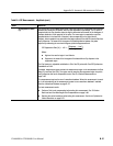
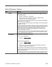
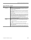
RZ RMS Jitter Jitter is the measure of time variance at the location where the signal crosses the mid-reference
level. RMS Jitter i s def ined as one standard deviat ion (σ) of that variance. The mean of the
histogram of t he crossing data dist ribution is Tcross.
RMS Jitter = Tcrossσ
The mid-reference level is adjustable and defaults to 50% of the RZ maximum pulse amplitude.
The jitt er measurement can be performed on the positive or negative slope. See Mid-reference
level on page B--69.
The slope can be selected to be the fi rst posi tive, the fi rst negat ive, or the first crossing (positive
or negative) in the region.
If enabled, measurement gates constrain the measurement region to the area between the Start
Gate (G1) and Stop Gate (G2). By default, the algorithm searches forward from the Start Gate
for the f irst speci fied edge, but the Direction of traversal can be reversed, so that the search will
be backward from the Stop Gate. See To Localize a Measurement on page 3--83.
This measurement requires the use of a waveform database. When this measurement is turned
on, it will automat ically set the measurement system to use a waveform database if available.
See Use a Waveform Database on page B--70.
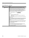
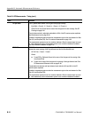
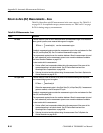
RZ +Width The time interval between the crossings of the rising and falling edges at the mid-reference
level.
+Width = Tcross2 – Tcross1
Where Tcross1 and Tcross2 are the mean of the histogram of the rising and falling
crossings.
The mid-reference level is adjustable and defaults to 50% of the RZ pulse amplitude.
If enabled, measurement gates constrain the measurement region to the area between the Start
Gate (G1) and Stop Gate (G2).
This measurement requires the use of a waveform database. When this measurement is turned
on, it will automat ically set the measurement system to use a waveform database if available.