


Appendix B: Automatic Measurements Reference
B-18
CSA8000B & TDS8000B User Manual
Table B- 4: RZ Measurements - Amplitude (cont.)
Name Definition
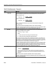
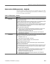
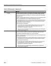
RZ Extinction Ratio (dB) The rati o of the average power levels of t he logic 1 level (High) to the logic 0 level (Low) of an
optical RZ signal, expressed in decibel s, dB. All level determinations are made within the RZ
Eye Aperture.
Where High and Low are the logical 1 and 0 levels. See RZ Eye Aperture Parameters
on B--62.
The Eye Aperture is adj ustable and defaults to 5% of the RZ pulse width.
If enabled, measurement gates constrain the measurement region to the area between the Start
Gate (G1) and Stop Gate (G2). See To Localize a Measurement on page 3--83.
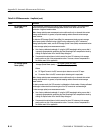
This measurement requires the use of a waveform database. When this measurement is turned
on, it will automat ically set the measurement system to use a waveform database if available.
See Use a Waveform Database on page B--70.
For best measurement results:
H Always perform a Dark Level compensation before taking this measurement. See To
Perform D ark-Level and User Wavelength Gain Compensat ions on page 3--98.
H Optimize the vertical resolution before taking this measurement. See To Optimize the
Vertical Resolution on page B--69.
RZ ExtRatio [dB] = 10 × log
Ꮛ
High
Low
Ꮠ
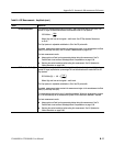
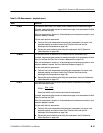
RZ Eye Height RZ Eye Height is a measure of how noise affects the vertical opening between the High and
Low levels of an RZ pulse. The RZ pulse is sampled within the Eye Aperture, where the High
and Low levels are determined as the mean of the histogram of the data distribution in the
upper and lower half of the pulse, respectively. The noise levels are characterized by σhigh and
σlow, the standard deviations from the mean for the High and Low levels.
RZ Eye height = (High – 3*σhigh) – (Low + 3 * σlow),
Where High and Low are the logical 1 and 0 levels, and σhigh and σlow are the standard
deviations.
The Eye Aperture is adj ustable and defaults to 5% of the RZ pulse width.
If enabled, measurement gates constrain the measurement region to the area between the Start
Gate (G1) and Stop Gate (G2).
This measurement requires the use of a waveform database. When this measurement is turned
on, it will automat ically set the measurement system to use a waveform database if available.
For best result s with t his measurement:
H Perform a Dark Level compensati on before taki ng this m easurement if the source of the
measured waveform is an optical channel. See To Perform Dark-Level and User
Wavelength Gain Compensations on page 3--98.
H Optimize the vertical resolution before taking this measurement. See To Optimize the
Vertical Resolution on page B--69.