


Appendix B: Automatic Measurements Reference
CSA8000B & TDS8000B User Manual
B-25
Table B- 4: RZ Measurements - Amplitude (cont.)
Name Definition
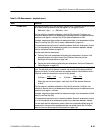
RZ RMS Noise One standard deviation of the data distribution sampled within a fixed width vertical slice located
at the center of the Eye Aperture at the High (logical 1) or Low (logical 0) levels.
RMS noise = Highσ or RMS noise = Lowσ
The Eye Aperture is adj ustable and defaults to 5% of the RZ pulse width. The High or Low
selection for Noise At control in the Measurement Setup dialog instructs the measurement to be
performed on the logical 1 or 0 l evels. See RZ Eye Aperture Parameters on B--62.
If enabled, measurement gates constrain the measurement region to the area between the Start
Gate (G1) and Stop Gate (G2). See To Localize a Measurement on page 3--83.
This measurement requires the use of a waveform database. When this measurement is turned
on, it will automat ically set the measurement system to use a waveform database if available.
See Use a Waveform Database on page B--70.
For best result s with t his measurement:
H Perform a Dark Level compensati on before taki ng this m easurement if the source of the
measured waveform is an optical channel. See To Perform Dark-Level and User
Wavelength Gain Compensations on page 3--98.
H Optimize the vertical resolution before taking this measurement. See How to Optimize the
Vertical Resolution on page B--70.
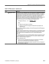
RZ Signal-to-Noise Ratio The ratio of the RZ pulse amplitude to the noise on either the High (logical 1) or Low (logical 0)
level. The dat a within the Eye Aperture is sampled, and the mean of the histogram yields the
High and Low levels. The noise is defined as one standard deviation of the distribution within a
fixed width verti cal slice located at the center of the Eye Aperture.
Where High and Low are the logical 1 and 0 levels. See RZ Eye Aperture Parameters
on B--62.
The Eye Aperture is adj ustable and defaults to 5% of the RZ pulse width. The High or Low
selection for Noise At control in the Measurement Setup dialog instructs the measurement to be
performed on the logical 1 or 0 l evels.
If enabled, measurement gates constrain the measurement region to the area between the Start
Gate (G1) and Stop Gate (G2).
This measurement requires the use of a waveform database. When this measurement is turned
on, it will automat ically set the measurement system to use a waveform database if available.
For best result s with t his measurement, perform a Dark Level compensation before taking this
measurement i f the source of the measured waveform is an optical channel. See To Perform
Dark-Level and User Wavelengt h Gain Compensations on page 3-- 98.
SፒNRatio=
(High − Low)
Highσ
or SፒNRatio=
(High − Low)
Lowσ