


3-14
Catalyst 2950 Desktop Switch Software Configuration Guide
78-14982-01
Chapter 3 Getting Started with CMS
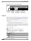
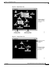
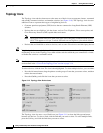
Topology View
Colors in the Topology View
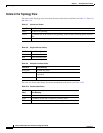
The colors of the Topology view icons show the status of the devices and links (see Table 3-7, Table 3-8,
and Table 3-9).
The color of a device label shows the cluster membership of the device (see Table 3-10).
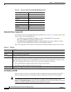
Table 3-7 Device Icon Colors
Icon Color Color Meaning
Green The device is operating.
Yellow
1
1. Available only on the cluster members.
The internal fan of the switch is not operating, or the switch is receiving power from an
RPS.
Red
1
The device is not operating.
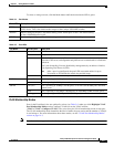
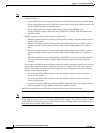
Table 3-8 Single Link Icon Colors
Link Color Color Meaning
Green Active link
Red Down or blocked link
Table 3-9 Multiple Link Icon Colors
Link Color Color Meaning
Both green All links are active.
One green; one red At least one link is active, and at least one other link is down
or blocked.
Both red All links are down or blocked.
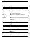
Table 3-10 Device Label Colors
Label
Color Color Meaning
Green A cluster member, either a member switch or the command switch
Cyan A candidate switch that is eligible to join the cluster
Yellow An unknown device or a device that is not eligible to join the cluster