


13-11
Catalyst 2950 Desktop Switch Software Configuration Guide
78-14982-01
Chapter 13 Configuring Optional Spanning-Tree Features
Understanding Optional Spanning-Tree Features
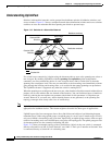
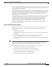
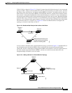
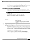
If link L1 fails as shown in Figure 13-8, Switch C cannot detect this failure because it is not connected
directly to link L1. However, because Switch B is directly connected to the root switch over L1, it detects
the failure, elects itself the root, and begins sending BPDUs to Switch C, identifying itself as the root.
When Switch C receives the inferior BPDUs from Switch B, Switch C assumes that an indirect failure
has occurred. At that point, BackboneFast allows the blocked port on Switch C to move immediately to
the listening state without waiting for the maximum aging time for the port to expire. BackboneFast then
transitions the Layer 2 interface on Switch C to the forwarding state, providing a path from Switch B to
Switch A. This switchover takes approximately 30 seconds, twice the Forward Delay time if the default
Forward Delay time of 15 seconds is set. Figure 13-8 shows how BackboneFast reconfigures the
topology to account for the failure of link L1.
Figure 13-8 BackboneFast Example After Indirect Link Failure
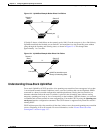
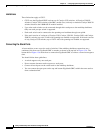
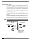
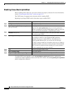
If a new switch is introduced into a shared-medium topology as shown in Figure 13-9, BackboneFast is
not activated because the inferior BPDUs did not come from the recognized designated bridge
(Switch B). The new switch begins sending inferior BPDUs that indicate it is the root switch. However,
the other switches ignore these inferior BPDUs, and the new switch learns that Switch B is the
designated bridge to Switch A, the root switch.
Figure 13-9 Adding a Switch in a Shared-Medium Topology
L1
L2 L3
Switch C
Switch A
(Root)
Switch B
Link failure
44964
BackboneFast transitions port
through listening and learning
states to forwarding state.
Switch A
(Root)
Switch C
Switch B
(Designated bridge)
Added switch
44965
Blocked port