


1-16
Catalyst 2950 Desktop Switch Software Configuration Guide
78-14982-01
Chapter 1 Overview
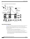
Network Configuration Examples
Hotel Network Configuration
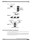
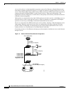
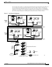
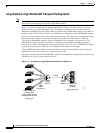
Figure 1-5 shows the Catalyst 2950 LRE switches in a hotel network environment with approximately
200 rooms. This network includes a PBX switchboard, a router, and high-speed servers.
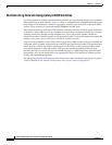
Connected to the telephone line in each hotel room is an LRE CPE device, such as a Cisco LRE CPE
device. The LRE CPE device provides:
• Two RJ-11 ports, one for connecting to the telephone jack on the wall and one for connecting to a
POTS telephone.
• One or more RJ-45 Ethernet ports for connecting to devices such as a customer’s laptop, the room’s
IP phone, the television set-top box, or a room environmental control device. A Cisco 575 LRE CPE
provides one Ethernet connection; a Cisco 585 LRE CPE provides four.
When connected to the CPE device, the Ethernet devices and room telephone share the same telephone
line.
Note All telephones not directly connected to the hotel room CPE device require microfilters with a 300-ohm
termination. Microfilters improve voice call quality when voice and data equipment are using the same
telephone line. They also prevent nonfiltered telephone rings and nonfiltered telephone transitions (such
as on-hook to off-hook) from interrupting the Ethernet connection.
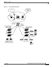
Through a patch panel, the telephone line from each room connects to a nonhomologated POTS splitter,
such as the Cisco LRE 48 POTS Splitter. The splitter routes data (high-frequency) and voice
(low-frequency) traffic from the telephone line to a Catalyst 2950 LRE switch and digital private branch
exchange (PBX). The PBX routes voice traffic to the PSTN.
If a PBX is not on-site, a homologated POTS splitter is required to connect directly to the PSTN.
Note Consult the regulations for connecting to the PSTN in your area.
If a connection to a phone network is not required at all, a splitter is not needed, and the switch can
connect directly to the patch panel.
Note Cisco LRE products can share lines with analog telephones, Integrated Services Digital Network (ISDN)
telephone network, and PBX switches that use the 0 to 700 kHz frequency range.
Data to and from the room devices (such as e-mail for the laptop and IP multicast traffic for the
television) are transferred through the LRE link, which is established between the CPE RJ-11 wall port
and the LRE port on an LRE switch. The upstream and downstream rates on the LRE link are controlled
by a profile configured on each LRE port. If the LRE switch was connected to the PSTN through a
homologated POTS splitter, all LRE ports would use an ANSI-compliant LRE profile named
LRE-998-15-4.
The Catalyst 2950 LRE switches are cascaded through their 10/100/1000 switch ports. Each switch also
has a 10/100/1000 connection to an aggregation switch, such as a 3550-12G switch. The aggregation
switch can connect to:
• Accounting, billing, and provisioning servers.
• A router that provides Internet access to the premises.