


3-12
Catalyst 2950 Desktop Switch Software Configuration Guide
78-14982-01
Chapter 3 Getting Started with CMS
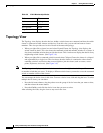
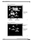
Topology View
Topology Icons
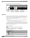
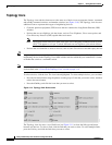
The Topology view and the cluster tree use the same set of device icons to represent clusters, command
and standby command switches, and member switches (see Figure 3-10). The Topology view also uses
additional icons to represent these types of neighboring devices:
• Customer premises equipment (CPE) devices that are connected to Long-Reach Ethernet (LRE)
switches
• Devices that are not eligible to join the cluster, such as Cisco IP phones, Cisco access points, and
Cisco Discovery Protocol (CDP)-capable hubs and routers
Note The System Switch Processor (SSP) card in the Cisco Integrated Communications System
(ICS) 7750 appears as a Layer 2 switch. SSP cards are not eligible to join switch clusters.
• Devices that are identified as unknown devices, such as some Cisco devices and third-party devices
Tip Neighboring devices are only displayed if they are connected to cluster members. To display
neighboring devices in the Topology view, either add the switch to which they are connected to a cluster,
or enable that switch as a command switch.
Note Candidate switches are distinguished by the color of their device label. Device labels and their colors
are described in the “Colors in the Topology View” section on page 3-14.
To select a device, click the icon. The icon is then highlighted. To select multiple devices, you can either:
• Press the left mouse button, drag the pointer over the group of icons that you want to select, and then
release the mouse button.
• Press the Ctrl key, and click the icons that you want to select.
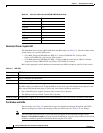
Figure 3-10 Topology-View Device Icons
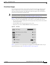
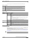
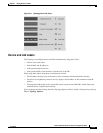
The Topology view also uses a set of link icons (see Figure 3-11) to show the link type and status
between two devices. To select a link, click the link that you want to select. To select multiple links,
press the Ctrl key, and click the links that you want to select.