


28-13
Catalyst 2950 Desktop Switch Software Configuration Guide
78-14982-01
Chapter 28 Troubleshooting
GBIC and SFP Module Security and Identification
GBIC and SFP Module Security and Identification
Cisco-approved Gigabit Interface Converter (GBIC) modules have a serial EEPROM that contains the
module serial number, the vendor name and ID, a unique security code, and cyclic redundancy check
(CRC). When a GBIC module is inserted in the switch, the switch software reads the EEPROM to check
the serial number, vendor name and vendor ID, and recompute the security code and CRC. If the serial
number, the vendor name or vendor ID, the security code, or CRC is invalid, the switch places the
interface in an error-disabled state.
Note If you are using a non-Cisco approved GBIC module, remove the GBIC from the switch, and replace it
with a Cisco-approved module.
After inserting a Cisco-approved GBIC or SFP module, use the errdisable recovery cause gbic-invalid
global configuration command to verify the port status, and enter a time interval for recovering from the
error-disabled state. After the elapsed interval, the switch brings the interface out of the error-disabled
state and retries the operation. For more information about the errdisable recovery command, refer to
the command reference for this release.
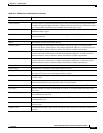
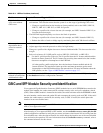
High Reed-Solomon
error count without
CRC errors
• Interleaver is helping Reed-Solomon error correction to function correctly in a noisy
environment. This situation means that the system is on the verge of generating CRC errors.
–
Change to a profile that has the interleaver feature enabled, such as the LRE-5, LRE-10,
LRE-15, LRE-10-1, LRE-10-3, or LRE-10-5 profile.
–
Change to a profile with a lower data rate (for example, use LRE-5 instead of LRE-15) to
increase the noise margin.
• The LRE link length and quality are close to the limit of operation.
–
Change to a profile with a lower data rate (for example, use LRE-5 instead of LRE-15).
–
Reduce the effect of stubs or bridge taps by terminating them with 300-ohm microfilters.
Ethernet performance
degradation due to
excessive network
latency
Interleaver introduces extra latency to increase noise margin.
• Adjust upper-layer network protocols to allow for high latency.
• Change to a profile with a higher data rate to increase link bandwidth. This decreases the noise
margin.
• Select a low-latency (LL) LRE profile, such as LRE-5LL, LRE-10LL, or LRE-15LL.
Note Use the LL private profiles with care. The LL profiles have the LL feature enabled and the
interleaver feature turned off. The LL feature does not delay data transmission, but it makes
data more susceptible to interruptions on the LRE link.
All other profiles, public and private, have the interleaver feature enabled and the LL
feature disabled. The interleaver feature provides maximum protection against small
interruptions on the LRE link but delays data transmission. For more information about the
LRE profiles, see the “Types of LRE Profiles” section on page 7-17.
LRE link quality
reduced in installations
with bundled cables
Cross-talk between the LRE links is causing all links to degrade. Disable unused LRE ports by using
the lre shutdown interface configuration command.
Table 28-4 LRE Port Problems (continued)
Problem Suspected Cause and Suggested Solution