


1-13
Catalyst 2950 Desktop Switch Software Configuration Guide
78-14982-01
Chapter 1 Overview
Network Configuration Examples
Collapsed Backbone and Switch Cluster Configuration
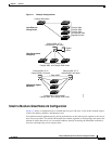
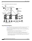
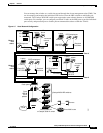
Figure 1-3 shows a configuration for a network of approximately 500 employees. This network uses a
collapsed backbone and switch clusters. A collapsed backbone has high-bandwidth uplinks from all
segments and subnetworks to a single device, such as a Gigabit switch, that serves as a single point for
monitoring and controlling the network. You can use a Catalyst 3550-12T-L3 switch, as shown, or a
Catalyst 3508G XL switch to create a Gigabit backbone. A Catalyst 3550-12T-L3 backbone switch
provides the benefits of inter-VLAN routing and allows the router to focus on WAN access.
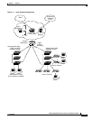
The workgroups are created by clustering all the Catalyst switches except the Catalyst 4908G-L3 switch.
Using CMS and Cisco switch clustering technology, you can group the switches into multiple clusters,
as shown, or into a single cluster. You can manage a cluster through the IP address of its active and
standby command switches, regardless of the geographic location of the cluster members.
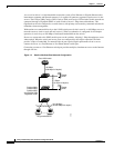
This network uses VLANs to segment the network logically into well-defined broadcast groups and for
security management. Data and multimedia traffic are configured on the same VLAN. Voice traffic from
the Cisco IP Phones are configured on separate voice VLAN IDs (VVIDs). You can have up to
four VVIDs per wiring closet. If data, multimedia, and voice traffic are assigned to the same VLAN, only
one VLAN can be configured per wiring closet. For any switch port connected to Cisco IP Phones,
802.1P/Q QoS gives forwarding priority to voice traffic over data traffic.
Grouping servers in a centralized location provides benefits such as security and easier maintenance.
The Gigabit connections to a server farm provide the workgroups full access to the network resources
(such as a call-processing server running Cisco CallManager software, a DHCP server, or an IP/TV
multicast server).
Cisco IP Phones are connected—using standard straight-through, twisted-pair cable with RJ-45
connectors—to the 10/100 inline-power ports on the Catalyst 3524-PWR XL switches and to the
10/100 ports on the Catalyst 2950 switches. These multiservice switch ports automatically detect if an
IP phone is connected. Cisco CallManager controls call processing, routing, and IP phone features and
configuration. Users with workstations running Cisco SoftPhone software can place, receive, and control
calls from their PCs. Using Cisco IP Phones, Cisco CallManager software, and Cisco SoftPhone
software integrates telephony and IP networks, and the IP network supports both voice and data.
Each 10/100 inline-power port on the Catalyst 3524-PWR XL switches provides –48 VDC power to the
Cisco IP Phone. The IP phone can receive redundant power when it also is connected to an AC power
source. IP phones not connected to the Catalyst 3524-PWR XL switches receive power from an AC
power source.