


14-17
Catalyst 2950 Desktop Switch Software Configuration Guide
78-14982-01
Chapter 14 Configuring VLANs
Configuring VLAN Trunks
• Disabling spanning tree on the native VLAN of an 802.1Q trunk without disabling spanning tree on
every VLAN in the network can potentially cause spanning-tree loops. We recommend that you
leave spanning tree enabled on the native VLAN of an 802.1Q trunk or disable spanning tree on
every VLAN in the network. Make sure your network is loop-free before disabling spanning tree.
Default Layer 2 Ethernet Interface VLAN Configuration
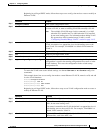
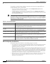
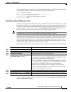
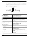
Table 14-5 shows the default Layer 2 Ethernet interface VLAN configuration.
Configuring an Ethernet Interface as a Trunk Port
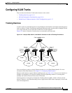
Because trunk ports send and receive VTP advertisements, to use VTP you must ensure that at least one
trunk port is configured on the switch and that this trunk port is connected to the trunk port of a second
switch. Otherwise, the switch cannot receive any VTP advertisements.
This section includes these procedures for configuring an Ethernet interface as a trunk port on the switch:
• Interaction with Other Features, page 14-17
• Defining the Allowed VLANs on a Trunk, page 14-19
• Changing the Pruning-Eligible List, page 14-20
• Configuring the Native VLAN for Untagged Traffic, page 14-20
Note The default mode for Layer 2 interfaces is switchport mode dynamic desirable. If the neighboring
interface supports trunking and is configured to allow trunking, the link is a Layer 2 trunk.
Interaction with Other Features
Trunking interacts with other features in these ways:
• A trunk port cannot be a secure port.
• Trunk ports can be grouped into EtherChannel port groups, but all trunks in the group must have the
same configuration. When a group is first created, all ports follow the parameters set for the first
port to be added to the group. If you change the configuration of one of these parameters, the switch
propagates the setting you entered to all ports in the group:
–
allowed-VLAN list
–
STP port priority for each VLAN
Table 14-5 Default Layer 2 Ethernet Interface VLAN Configuration
Feature Default Setting
Interface mode switchport mode dynamic desirable
Allowed VLAN range VLANs 1 to 4094 when the EI is installed and 1 to
1005 when the SI is installed
VLAN range eligible for pruning VLANs 2 to 1001
Default VLAN (for access ports) VLAN 1
Native VLAN (for 802.1Q trunks) VLAN 1