


26-2
Catalyst 2950 Desktop Switch Software Configuration Guide
78-14982-01
Chapter 26 Configuring QoS
Understanding QoS
• Video wizard—Gives traffic that originates from specified video servers a higher priority than the
priority of data traffic. The wizard assumes that the video servers are connected to a single device
in the cluster. Refer to the video wizard online help for procedures about using this wizard.
This chapter consists of these sections:
• Understanding QoS, page 26-2
• Configuring QoS, page 26-9
• Displaying QoS Information, page 26-28
• QoS Configuration Examples, page 26-29
Understanding QoS
This section describes how QoS is implemented on the switch. If you have the SI installed on your
switch, some concepts and features in this section might not apply. For a list of available features, see
Table 26-1 on page 26-1.
Typically, networks operate on a best-effort delivery basis, which means that all traffic has equal priority
and an equal chance of being delivered in a timely manner. When congestion occurs, all traffic has an
equal chance of being dropped.
When you configure the QoS feature, you can select specific network traffic, prioritize it according to
its relative importance, and use congestion-management and congestion-avoidance techniques to
provide preferential treatment. Implementing QoS in your network makes network performance more
predictable and bandwidth utilization more effective.
The QoS implementation is based on the DiffServ architecture, an emerging standard from the Internet
Engineering Task Force (IETF). This architecture specifies that each packet is classified upon entry into
the network. The classification is carried in the IP packet header, using 6 bits from the deprecated IP
type-of-service (ToS) field to carry the classification (class) information.
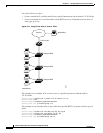
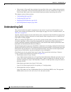
Classification can also be carried in the Layer 2 frame. These special bits in the Layer 2 frame or
a Layer 3 packet are described here and shown in Figure 26-1:
• Prioritization values in Layer 2 frames
Layer 2 802.1Q frame headers have a 2-byte Tag Control Information field that carries the class of
service (CoS) value in the three most-significant bits, which are called the User Priority bits. On
interfaces configured as Layer 2 802.1Q trunks, all traffic is in 802.1Q frames except for traffic in
the native VLAN.
Other frame types cannot carry Layer 2 CoS values.
Layer 2 CoS values range from 0 for low priority to 7 for high priority.
• Prioritization bits in Layer 3 packets
Layer 3 IP packets can carry a Differentiated Services Code Point (DSCP) value. The supported
DSCP values are 0, 8, 10, 16, 18, 24, 26, 32, 34, 40, 46, 48, and 56.