


27-2
Catalyst 2950 Desktop Switch Software Configuration Guide
78-14982-01
Chapter 27 Configuring EtherChannels
Understanding EtherChannels
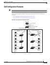
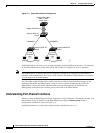
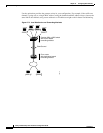
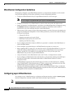
Figure 27-1 Typical EtherChannel Configuration
Each EtherChannel can consist of up to eight compatibly configured Ethernet interfaces. All interfaces
in each EtherChannel must be the same speed, and all must be configured as Layer 2 interfaces.
Note The network device to which your switch is connected can impose its own limits on the number of
interfaces in the EtherChannel. For Catalyst 2950 switches, the number of EtherChannels is limited to
six with eight ports per EtherChannel.
If a link within an EtherChannel fails, traffic previously carried over that failed link changes to the
remaining links within the EtherChannel. A trap is sent for a failure, identifying the switch, the
EtherChannel, and the failed link. Inbound broadcast and multicast packets on one link in an
EtherChannel are blocked from returning on any other link of the EtherChannel.
Understanding Port-Channel Interfaces
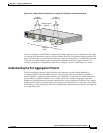
When you create an EtherChannel for Layer 2 interfaces, a logical interface is dynamically created. You
then manually assign an interface to the EtherChannel by using the channel-group interface
configuration command as shown in Figure 27-2.
Each EtherChannel has a logical port-channel interface numbered from 1 to. 6.
Catalyst 8500, 6000,
5500, or 4000
series switch
Catalyst 3550-12T
switch
Gigabit EtherChannel
Catalyst 3550-12T
switch
Workstations
10/100
Switched
links
74618
Catalyst 2950G-24
switch
Workstations
10/100
Switched
links
1000BASE-X 1000BASE-X