


3-6
Catalyst 2950 Desktop Switch Software Configuration Guide
78-14982-01
Chapter 3 Getting Started with CMS
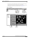
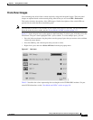
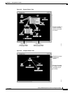
Front Panel View
Figure 3-5 Front Panel View from a 2950 non-LRE Standalone Switch
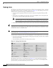
Cluster Tree
The cluster tree (see Figure 3-2 for LRE switches and Figure 3-3 for non-LRE switches) appears in the
left frame of the Front Panel view and shows the name of the cluster and a list of its members. The
sequence of the cluster-tree icons (see Figure 3-6) mirror the sequence of the Front-Panel images. You
can change the sequence by selecting View > Arrange Front Panel. The colors of the devices in the
cluster tree show the status of the devices (see Table 3-1).
If you want to configure switch or cluster settings on one or more switches, select the appropriate
Front-Panel image.
• To select a front-panel image, click either the cluster-tree icon or the corresponding front-panel
image. The front-panel image is then highlighted with a yellow outline.
• To select multiple front-panel images, press the Ctrl key, and left-click the cluster-tree icons or the
front-panel images. To deselect an icon or image, press the Ctrl key, and left-click the icon or image.
If the cluster has many switches, you might need to scroll down the window to display the rest of the
front-panel images. Instead of scrolling, you can click an icon in the cluster tree, and CMS then scrolls
and displays the corresponding front-panel image.
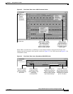
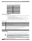
Figure 3-6 Cluster-Tree Icons
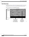
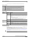
2950-24
Right-click a port to
display the port pop-up
menu, and select an
option to view or change
port-related settings.
Press Ctrl, and then
left-click ports to select
multiple ports. The color
of the port LED reflects
port or link status.
LEDs display the
current port mode
and the status of the
switch and
connected RPS.
Left-click the Mode
button to change
the meaning of the
port LEDs.
65719
2950-24
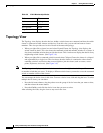
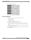
Table 3-1 Cluster Tree Icon Colors
Color Device Status
Green Switch is operating normally.
Yellow The internal fan of the switch is not operating, or the switch is receiving power from an RPS.
Red Switch is not powered up, has lost power, or the command switch is unable to communicate
with the member switch.