


3-10
Catalyst 2950 Desktop Switch Software Configuration Guide
78-14982-01
Chapter 3 Getting Started with CMS
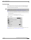
Topology View
Topology View
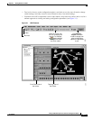
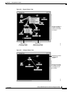
The Topology view displays how the devices within a switch cluster are connected and how the switch
cluster is connected to other clusters and devices. From this view, you can add and remove cluster
members. This view provides two levels of detail of the network topology:
• When you right-click a cluster icon and select Expand Cluster, the Topology view displays the
switch cluster in detail. This view shows the command switch and member switches in a cluster. It
also shows candidate switches that can join the cluster. This view does not display the details of any
neighboring switch clusters. (See Figure 3-8).
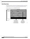
• When you right-click a command-switch icon and select Collapse Cluster, the cluster is collapsed
and represented by a single icon. The view shows how the cluster is connected to other clusters,
candidate switches, and devices that are not eligible to join the cluster (such as routers, access
points, IP phones, and so on). (See Figure 3-9).
Note The Topology view displays only the switch cluster and network neighborhood of the specific command
or member switch that you access. To display a different switch cluster, you need to access the command
switch or member switch of that cluster.
You can arrange the device icons in this view. To move a device icon, click and drag the icon. To select
multiple device icons, you can either:
• Press the left mouse button, drag the pointer over the group of device icons that you want to select,
and then release the mouse button.
• Press the Ctrl key, and click the device icons that you want to select.
After selecting the icons, drag the icons to any area in the view.
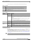
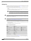
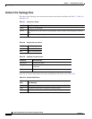
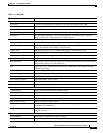
Table 3-6 VLAN Membership Modes
Mode Color
Static access Light green
Dynamic access Pink
802.1Q trunk Peach
Negotiate trunk White